Refer to p268), External device setup manual – IDEC High Performance Series User Manual
Page 286
Chapter 2
268
External Device Setup Manual
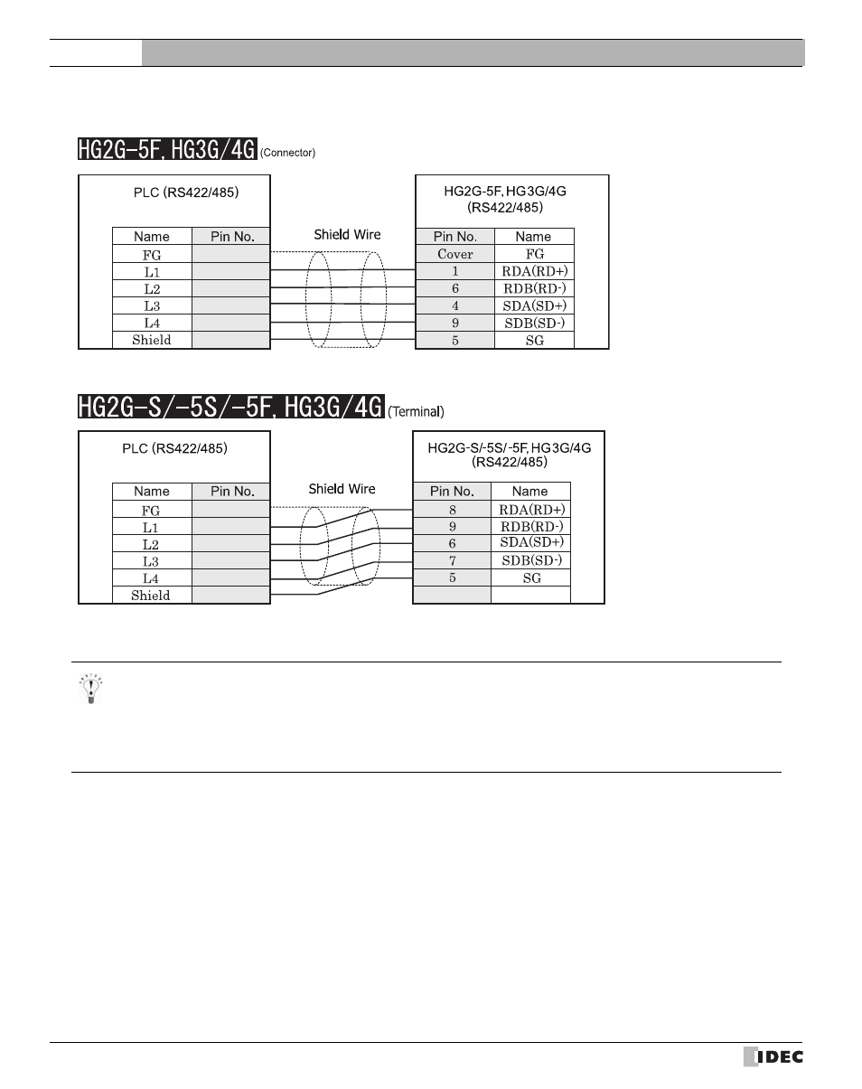
7.3.2
Connection Diagram 2: RS485 4-wire Link Unit to MICRO/I
Screw terminal block
D-sub, 9P connector plug type
Screw terminal block
Terminal
- We recommend that you switch on the termination resistor on the PLC Link Unit side for long-distance transmission con-
nection cable is available.
- There is no pin number corresponding to TERM on the HG2G-S/-5S/-5F, HG3G/4G. When inserting a termination resis-
tor, use a communication switch. For the setting of the switch, refer to Chapter 1 "3 Important Points Regarding Wiring"
on page 19.
This manual is related to the following products: