2 system configuration, System configuration, External device setup manual – IDEC High Performance Series User Manual
Page 281
263
7 SHARP
2
2
2
2
2
2
2
2
2
2
2
2
2
2
2
Con
nection
to a PLC
External Device Setup Manual
7.2
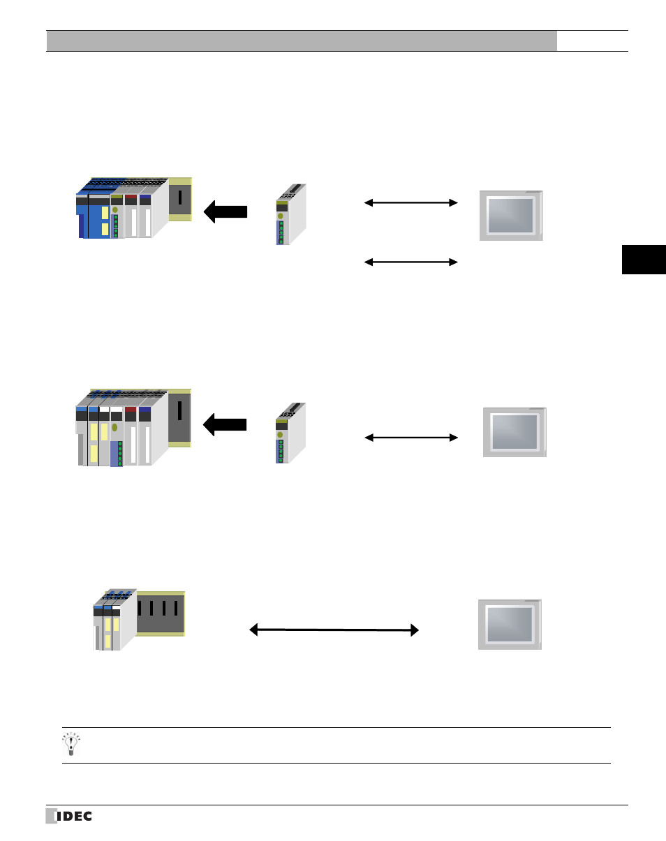
System Configuration
This is the system configuration for the connection of SHARP PLCs to the MICRO/I.
7.2.1
JW20/30 Series (using link module)
7.2.2
JW50/70/100 Series (using link module)
7.2.3
JW50/70/100 Series (using communication port)
Connect to the communication port of CPU unit.
JW-21CM
RS485 2-wire
Connection Diagram 1
MICRO/I
RS485 4-wire
Connection Diagram 2
JW-21CU, JW-22CU
JW-31CUH/H1
JW-32CUH/H1
JW-33CUH/H1/H2/H3
JW-10CM
MICRO/I
RS485 4-wire
Connection Diagram 2
JW-50CU/CUH
JW-70CU/CUH
JW-100CU/CUH
MICRO/I
RS232C
Connection Diagram 3
JW-22CU
JW-70CU/CUH
JW-100CU/CUH
This manual is related to the following products: