Refer to p419) – IDEC High Performance Series User Manual
Page 437
419
16 YOKOGAWA
2
2
2
2
2
2
2
2
2
2
2
2
2
2
2
Con
nection
to a PLC
External Device Setup Manual
16.3.2
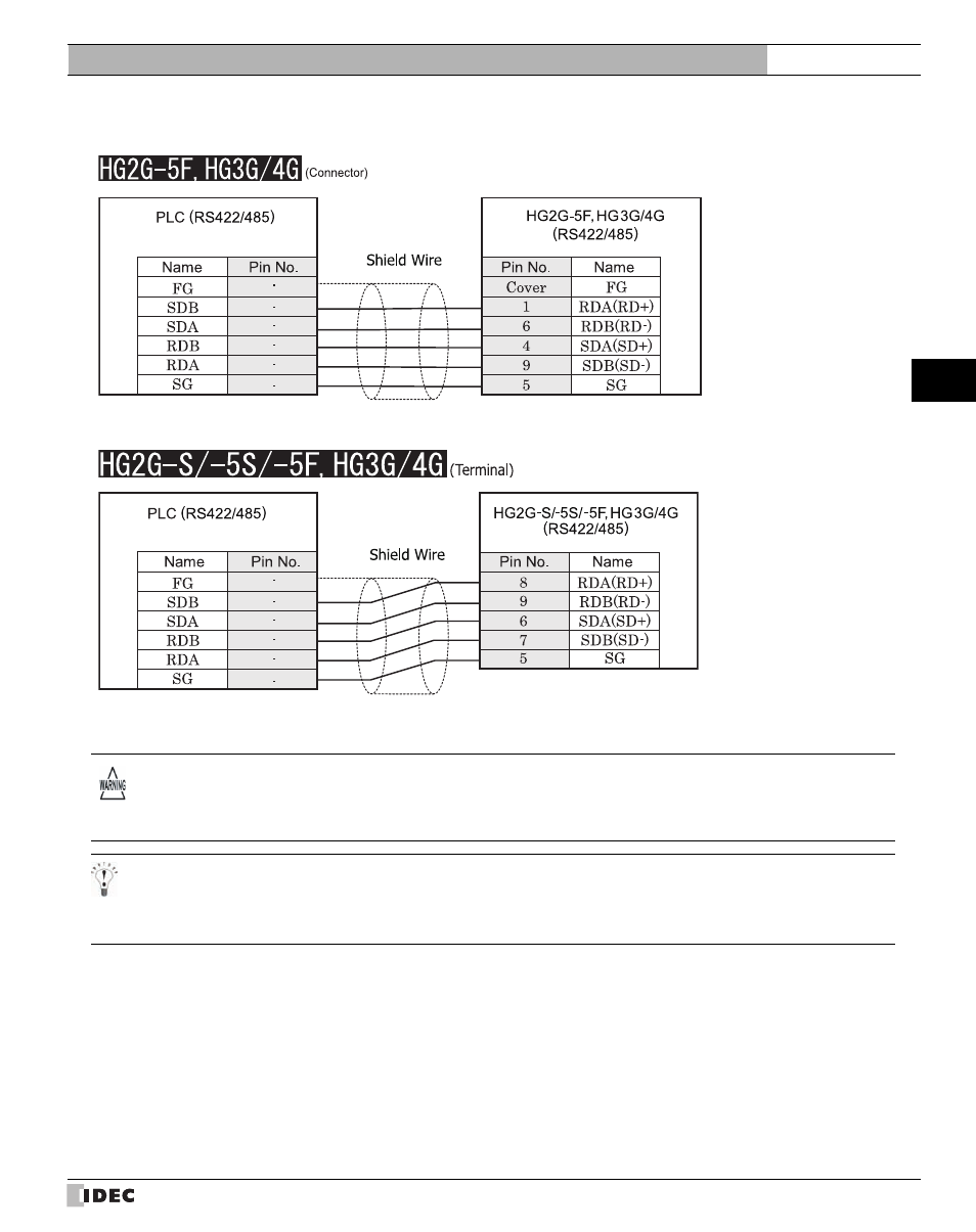
Connection Diagram 2: FA-M3 F3LC11-2N - MICRO/I
There is no pin number corresponding to TERM on the HG2G-S/-5S/-5F, HG3G/4G. When inserting a termination resistor,
use a communication switch. For the setting of the switch, refer to Chapter 1 "3 Important Points Regarding Wiring" on
page 19.
Screw terminal block
D-sub, 9P connector plug type
Screw terminal block
Terminal
- In MICRO/I and PLC, the name of A pole and B pole is reverse.
- When you use the Terminal Block type of HG2G-S/-5S/-5F, HG3G/4G, make sure to configure the Hardware Flow con-
trol to NONE.
This manual is related to the following products: