External device setup manual – IDEC High Performance Series User Manual
Page 120
Chapter 2
102
External Device Setup Manual
2.5.3
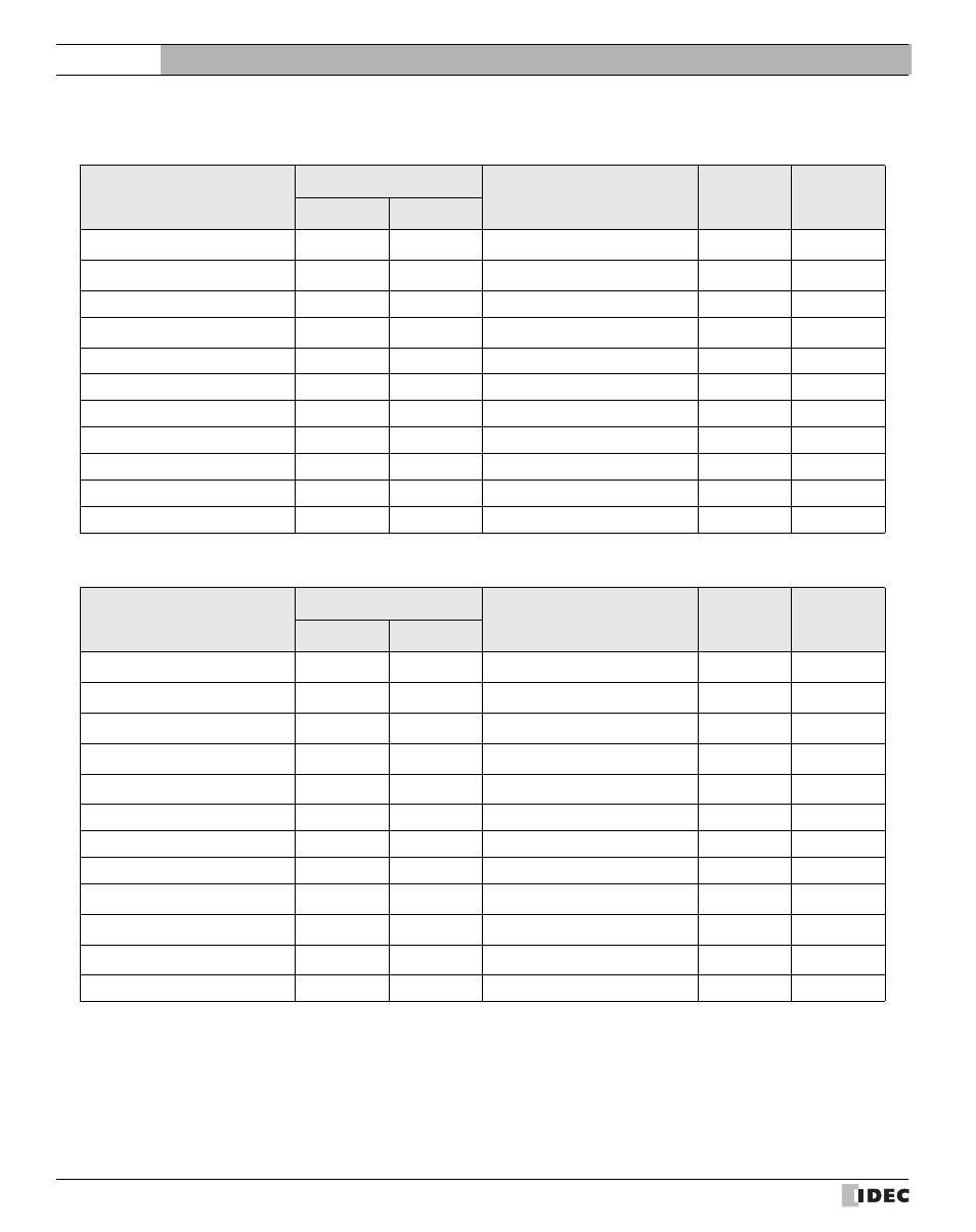
MELSEC-AnA (CPU)
Bit Device
Device Name
Device Symbol
Address Range
Read
/Write
Address
Gradual
MICRO/I
PLC
Input Relay
X
X
0 - 7FF
R
*1
*1. Set this device using hexadecimal.
Output Relay
Y
Y
0 - 7FF
R/W
Internal Relay
M
M
0 - 8191
R/W
Link Relay
B
B
0 - 7FF
R/W
Latch Relay
L
L
0 - 8191
R/W
Timer (contact)
TS
T
0 - 2047
R
Timer (coil)
TC
T
0 - 2047
R/W
Counter (contact)
CS
C
0 - 1023
R
Counter (coil)
CC
C
0 - 1023
R/W
Special Internal Relay
SM
SM
9000 - 9255
R
Annunciator
F
F
0 - 2047
R/W
Word Device
Device Name
Device Symbol
Address Range
Read
/Write
Address
Gradual
MICRO/I
PLC
Input Relay
WX
X
0 - 7F0
R
*1
*2
*1. Set this device using hexadecimal.
*2. Set this device using a multiplier of 16.
Output Relay
WY
Y
0 - 7F0
R/W
Internal Relay
WM
M
0 - 8176
R/W
Link Relay
WB
B
0 - 7F0
R/W
Latch Relay
WL
L
0 - 8176
R/W
Timer (current value)
TN
T
0 - 2047
R
Counter (current value)
CN
C
0 - 1023
R
Data Register
D
D
0 - 6143
R/W
Link Register
W
W
0 - FFF
R/W
Annunciator
WF
F
0 - 2032
R/W
Special Internal Relay
WSM
SM
9000 - 9240
R
Special Register
SD
SD
9000 - 9255
R