20 ls industrial systems, 1 connection table, Connection table – IDEC High Performance Series User Manual
Page 518: External device setup manual
Chapter 2
500
External Device Setup Manual
20 LS Industrial Systems
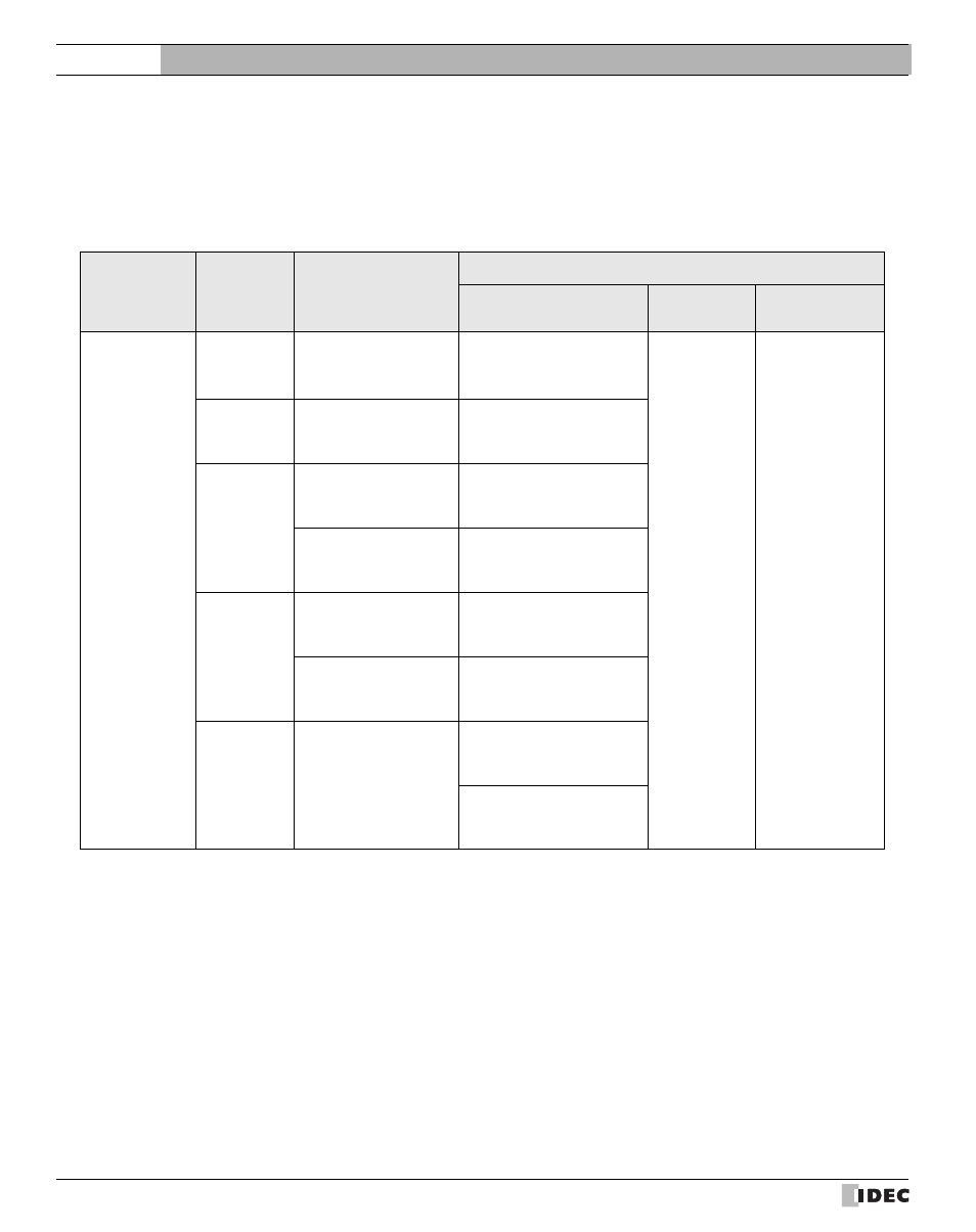
20.1 Connection Table
20.1.1
Compatible PLCs
Series Name
System
(CPU unit)
Link Unit
WindO/I-NV2 Settings
Interface
Flow
Control
Host I/F Driver
MASTER-K
K10S1
Not required
(Connects to CPU unit)
RS232C
Connection Diagram 1
(refer to P503)
None
MASTER-K
K80S,
K120S,
K200S,
Not required
(Connects to CPU unit)
RS232C
Connection Diagram 2
(refer to P505)
G7L-CUEB
RS232C
Connection Diagram 3
(refer to P507)
G7L-CUEC
RS422/485 4-wire
Connection Diagram 4
(refer to P509)
K200S
G6L-CUEB
RS232C
Connection Diagram 3
(refer to P507)
G6L-CUEC
RS422/485 4-wire
Connection Diagram 4
(refer to P509)
K300S
*1
*1. We tested with the PLC of these parts.
G4L-CUEA
RS232C
Connection Diagram 3
(refer to P507)
RS422/485 4-wire
Connection Diagram 4
(refer to P509)