Yaskawa MP920 Motion Module User Manual
Page 57
2.3 Position Control
2-31
2
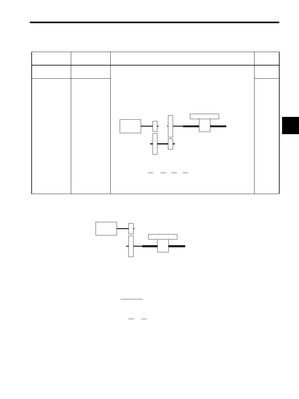
Electronic Gear Parameter Setting Example (A): With Ball Screw
In the above machine system, if the requirement is reference unit = output unit = 0.001 mm,
the setting of each parameter will be as follows:
•
•
• No.21 = 7
• No.22 = 5
No.21
Servomotor Gear
Ratio
• These parameters are used to set the gear ratio between the motor and the
load. When the motor axis has rotated m times and the mechanical config-
uration allows the load axis to rotate n times, set the following
values: No.21 = m rotations
No.22 = n rotations
• Setting range: 1 to 65,535 [rotations]
Setting Examples
1
No.22
Machine Gear
Ratio
1
Table 2.12 Electronic Gear Parameters and Constant Table (cont’d)
Servo Fixed
Parameter No.
Name
Description
Initial
Value
Motor axis
m rotations
Load axis n rotations
7 rotations
3 rotations
4 rotations
9 rotations
Gear ratio = =
×
=
Therefore, set the following values: No. 21 = 21
No. 22 = 4
n
m
3
7
4
9
4
21
Motor
m
7 rotations
Ball screw pitch
P = 6 mm/rotation
5 rotations
n
No.19 =
=
6000
6 mm
0.001 mm
Gear ratio = =
n
m
5
7
- Tag Generator (30 pages)
- MP3300iec (82 pages)
- 1000 Hz High Frequency (18 pages)
- 1000 Series (7 pages)
- PS-A10LB (39 pages)
- iQpump Micro User Manual (300 pages)
- 1000 Series Drive Option - Digital Input (30 pages)
- 1000 Series Drive Option - CANopen (39 pages)
- 1000 Series Drive Option - Analog Monitor (27 pages)
- 1000 Series Drive Option - CANopen Technical Manual (37 pages)
- 1000 Series Drive Option - CC-Link (38 pages)
- 1000 Series Drive Option - CC-Link Technical Manual (36 pages)
- 1000 Series Drive Option - DeviceNet (37 pages)
- 1000 Series Drive Option - DeviceNet Technical Manual (81 pages)
- 1000 Series Drive Option - MECHATROLINK-II (32 pages)
- 1000 Series Drive Option - Digital Output (31 pages)
- 1000 Series Drive Option - MECHATROLINK-II Technical Manual (41 pages)
- 1000 Series Drive Option - Profibus-DP (35 pages)
- AC Drive 1000-Series Option PG-RT3 Motor (36 pages)
- Z1000U HVAC MATRIX Drive Quick Start (378 pages)
- 1000 Series Operator Mounting Kit NEMA Type 4X (20 pages)
- 1000 Series Drive Option - Profibus-DP Technical Manual (44 pages)
- CopyUnitManager (38 pages)
- 1000 Series Option - JVOP-182 Remote LED (58 pages)
- 1000 Series Option - PG-X3 Line Driver (31 pages)
- SI-EN3 Technical Manual (68 pages)
- JVOP-181 (22 pages)
- JVOP-181 USB Copy Unit (2 pages)
- SI-EN3 (54 pages)
- SI-ET3 (49 pages)
- MECHATROLINK-III (35 pages)
- EtherNet/IP (50 pages)
- SI-EM3 (51 pages)
- 1000-Series Option PG-E3 Motor Encoder Feedback (33 pages)
- 1000-Series Option SI-EP3 PROFINET (56 pages)
- PROFINET (62 pages)
- AC Drive 1000-Series Option PG-RT3 Motor (45 pages)
- SI-EP3 PROFINET Technical Manual (53 pages)
- A1000 Drive Option - BACnet MS/TP (48 pages)
- 120 Series I/O Modules (308 pages)
- A1000 12-Pulse (92 pages)
- A1000 Drive Software Technical Manual (16 pages)
- A1000 Quick Start (2 pages)
- JUNMA Series AC SERVOMOTOR (1 page)
- A1000 Option DI-101 120 Vac Digital Input Option (24 pages)