2 parameter list by module, 1 motion fixed parameters – Yaskawa MP920 Motion Module User Manual
Page 125
4.2 Parameter List by Module
4-5
4
4.2
Parameter List by Module
This section describes the meaning and availability of each parameter according to the model of
Motion Module.
4.2.1
Motion Fixed Parameters
Motion fixed parameters are set only once unless there is a configurational, specification, or
other machine-related change. They are set from the Fixed Parameter Setting Window on the
MPE720.
Motion fixed parameters cannot be changed if bit 0 of the RUN command (OW01) is ON.
Position and other data will be initialized every time a motion fixed parameter is changed.
IMPORTANT
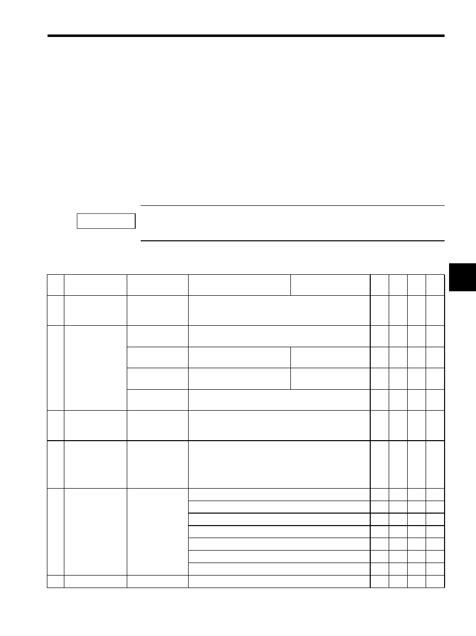
Table 4.2 Motion Fixed Parameters
No.
Name
Setting Range/
Bit Name
Meaning
Remarks
SVA
-01A
SVA
-02
A
SVB
-01
PO-
01
1
Axis
Selection
(USESEL)
0 or 1
(Default = 0)
0: Not used selection
1: Use selection
√
√
√
√
2
PG Input
Signal Form
Selections
(PGSEL)
Bits 0 to 7:
Not used.
−
−
−
−
−
Bit 8: ABPISEL
Pulse-A/B Input Signal Polarity
Selection
0: Positive logic
1: Negative logic
√
√
−
−
Bit 9: CPISEL
Pulse-C Input Signal Polarity
Selection
0: Positive logic
1: Negative logic
√
√
−
−
Bits 10 to 15:
Not used.
−
−
−
−
−
3
Encoder Selection
(ENCSEL)
0 to 2
(Default = 0)
0: Incremental encoder
1: Absolute encoder
2: Absolute encoder used as an incremental encoder
√
√
√
−
4
Rotation Direction
Selection with an
Absolute
Encoder
(DIRINV)
0 or 1
(Default = 0)
0: Forward direction selection
1: Reverse direction selection
√
√
−
−
5
Pulse Counting
Mode Selection
(PULMODE)
0 to 6
(Default = 6)
0: Sign,
×1
√
√
−
−
1: Sign,
×2
√
√
−
−
2: Up/Down,
×1
√
√
−
−
3: Up/Down,
×2
√
√
−
−
4: A/B mode,
×1
√
√
√
−
5: A/B mode,
×2
√
√
√
−
6: A/B mode,
×4
√
√
√
−
6
Not used.
−
−
−
−
−
−