Yaskawa MP920 Motion Module User Manual
Page 43
2.2 Control Modes
2-17
2
1. Set the motion fixed parameters according to the user’s machine.
* 1. Valid only with an SVB-01 Module.
* 2. Valid only with an SVA-02A Module.
2. Set the motion parameters to be used in the phase control mode. Use the user program to
control the reference speed so that no shock occurs.
The following three methods can be used to set the motion setting parameters.
• Using the MPE720 Setting Parameter Window
• Using a ladder logic program
• Using a motion program
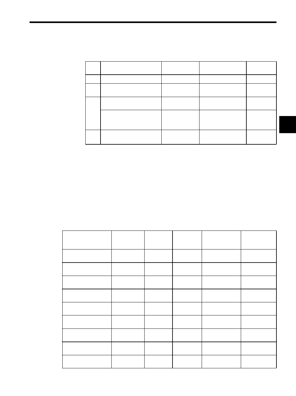
Table 2.6 shows the related parameters when the phase control mode is used.
* Valid only with an SVA-02A Module.
Table 2.5 Examples of Fixed Parameters
No.
Name
Setting Range
Meaning
Setting
Example
7
Rated Motor Speed Setting
1 to 32000
Rated motor speed
3000 min
-1
8
Number of Feedback Pulses per
Motor Rotation
4 to 65532
Number of pulses
before multiplication
2048
9
D/A Output Voltage at 100%
Speed
0.001 to 10.000
0.001 = 0.001 V
1 = 1 V
6.000 V
Number of Feedback Pulses per
Motor Rotation
(For high-resolution)
*1
4 to 2147483647
1 = 1 pulse/rev
2048 pulses/
rev
10
D/A Output Voltage at 100%
Torque Limit
*2
0.001 to 10.000
0.001 = 0.001 V
1 = 1 V
3.000 V
Table 2.6 Examples of Setting Parameters
Name
Register No.
Setting
Range
Meaning
Electronic Shaft
Setting Example
Electronic Cam
Setting
Example
Positive Torque Limit
Setting (TLIMP)*
OW02
-327.68 to
327.67
0.01 = 0.01%
1 = 1%
-100.00
(-100.00%)
-100.00
(-100.00%)
Positive Speed Limiter
Setting (NLIMP)
OW04
0.00 to
327.67
0.01 = 0.01%
1 = 1%
130.00
(130.00%)
130.00
(130.00%)
Negative Speed Limit-
er Setting (NLIMN)
OW05
0.00 to
327.67
0.01 = 0.01%
1 = 1%
130.00
(130.00%)
130.00
(130.00%)
Error Count Alarm De-
tection Setting (EOV)
OW0F
0 to 65535
1 = 1 pulse
65535
65535
Speed Reference
Setting (NREF)
OW15
-327.68 to
327.67
0.01 = 0.01%
1 = 1%
50.00
(50.00%)
Set by the ladder
logic program.
Phase Bias Setting
(PHBIAS)
OL16
-2
31
to 2
31
-1
1 = 1 pulse
Set by the ladder
logic program.
Set by the ladder
logic program.
Speed Compensation
Setting (NCOM)
OW18
-327.68 to
327.67
0.01 = 0.01%
1 = 1%
0.00
0.00
Proportional Gain
Setting (PGAIN)
OW19
0.0 to 3276.7 0.1 = 0.1 /s
1 = 1 /s
1.5
(1.5)
250.0
(250.0)
Integral Time Setting
(TI)
OW1A
0 to 32767
1 = 1 ms
300
(300 ms)
0
(0 ms)