Yaskawa MP920 Motion Module User Manual
Page 229
5.4 SVA-01A and SVA-02A Parameters
5-87
5
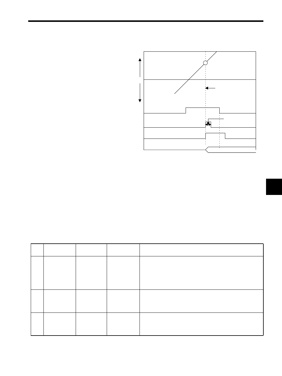
* 1. DI Latch Request = operating mode (OW00, bit 3)
* 2. DI Latch Completed Signal = operating status (IW00, bit 3)
* 3. Machine Coordinate System Latch Position = position when DI was
detected (IL06)
The machine coordinate system latch position is also stored for position control via
motion commands, i.e., when the following commands are executed: the external posi-
tioning motion command (EX_POSING: OW
20 = 2) and the motion program EXM
command. When executed, the axis moves either the External Positioning Travel Dis-
tance (OL
24) or the travel distance specified in the motion program and the axis
stops.
DIINT
Hardware latch
Using the Special Discrete Input
Counter count
register
DI Latch Request *1
External signal D17
DI Latch Completed Signal *2
Machine Coordinate System
Latch Position *3
0
(+)
(-)
0.5ms min.
DIINT
Table 5.7 Motion Monitoring Parameters (cont’d)
No.
Name
Register
Number
Setting Range/
Bit Name
Description
3
Calculated
Position in
Machine
Coordinate
System
(CPOS)
IL02
-2
31
to 2
31
-1
Indicates the calculated position in a machine coordinate system con-
trolled by SVA Modules. Normally the position data indicated at this
register is the target position for each scan.
See 2 of Supplemental Explanation 4.
5
Target Posi-
tion Difference
Monitor (PT-
GDIF)
IL04
-2
31
to 2
31
-1
Indicates the amount cleared every scan.
7
Machine Coor-
dinate System
Latch Position
(LPOS)
IL06
-2
31
to 2
31
-1
Indicates the current position the instant the DI latch signal turned
ON.
See 2 of Supplemental Explanation 4.