Led indicator 2 – Yaskawa MP920 Motion Module User Manual
Page 240
6.1 SVB-01 Module
6-5
6
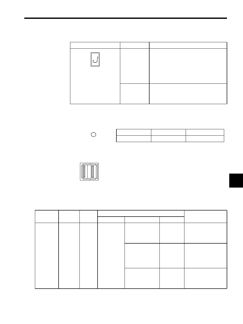
LED Indicator 2
The TRX indicator displays the communications status of the SVB-01 Module.
MECHATROLINK Connector (CN1)
Connector Specifications
The following table shows the specifications of the connectors shown above.
Alarm
Displayed when the following errors occur at one
of the four axes (axes 1 to 14).
• Motion setting parameter setting error (Refer to
IB001.)
• Alarm occurs (Refer to IL22.)
• Motion command abnormal-end status (when
IB155 is ON)
Abnormal
Displayed when the following error occurs at one
of the four axes (axes 1 to 14).
Fixed motion parameter setting error (Refer to
IB002.)
(cont’d)
Display
Category
Meaning
LED Name
LED Color
Meaning when Lit
TRX
Green
Transmission enabled
Use MECHATROLINK cables (JEPMC-W6000-A3 or JEPMC-W6000-
) to connect SERVOPACKs or IO350 stations.
TRX
Name
Connector
Name
Number
of Pins
Connector
Cable
On Module
On Cable
Manufacturer
MECHA-
TROLINK
Connector
CN1
4
DUSB-APA42-
T11
• USB-USB type
• Connector
DUSB-
APA41-B1-C50
DDK
JEPMC-W6000-A3
(0.3 m)
• USB-loose wire
type
• Connector
DUSB-
APA41-B1-C50
DDK
JEPMC-W6010-01 (1 m)
JEPMC-W6010-03 (3 m)
JEPMC-W6010-05 (5 m)
• USB terminator
• Connector body
DUSB-
APA41-B1-C50
DDK
JEPMC-W6020