3 motion monitoring parameters – Yaskawa MP920 Motion Module User Manual
Page 225
5.4 SVA-01A and SVA-02A Parameters
5-83
5
5.4.3
Motion Monitoring Parameters
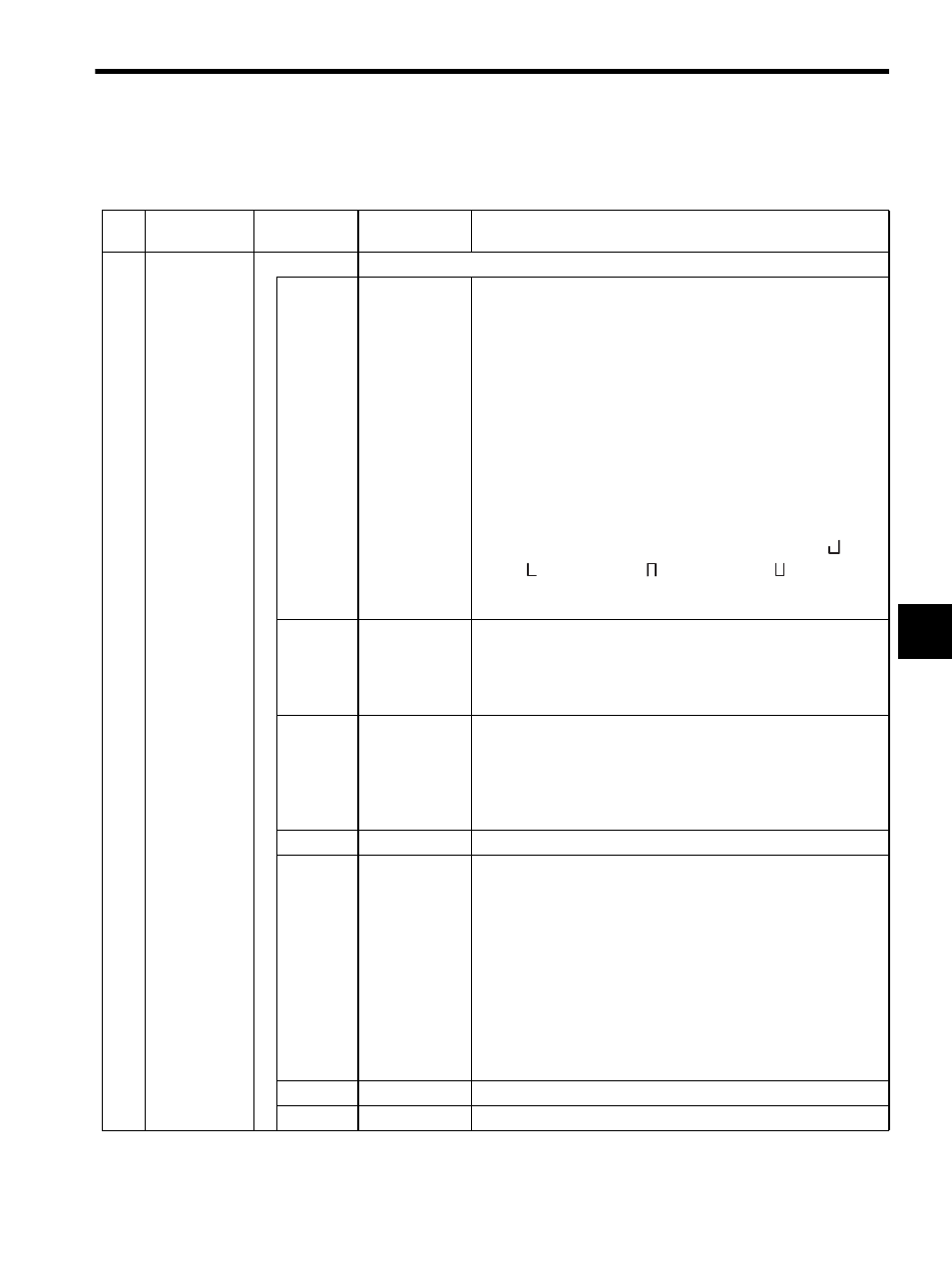
Table 5.7 Motion Monitoring Parameters
No.
Name
Register
Number
Setting Range/
Bit Name
Description
1
RUN Status
(RUNSTS)
IW00
Monitors SVA Module operating status. The bit configuration is described below.
Bit 0
Error Counter
Over (EOVER)
This bit is valid in Position Control Mode, Zero Point Return Mode,
and Phase Control Mode.
Turns ON when the IL0A: Position Error exceeds the OW0F:
Error Counter Alarm Detection Setting.
Note: Because control will not be interrupted, create a user pro-
gram that will monitor this bit and perform other processing
if application-specific processing, such as emergency stop, is
required.
The following items are potential causes for error alarms.
1. OW0F: Error Count Alarm Detection Setting is set too low.
2. The Servomotor is not operating.
3. Operation according to set references failed because the load in
the machine system is too heavy.
If an error occurs, the SVA Module indicators will indicate (
) (first
axis), (
) (second axis), (
) (third axis) and (
) (fourth axis).
The display will return to OFF when the error condition is removed
and bit 6 of OW00: Alarm Clear turns ON.
Bit 1
Motion Setting
Parameter
Setting Error
(PRMERR)
Turns ON when one or more of the motion setting parameters
(OW00 to OW3F) is set outside the setting range. In this
case, the most recent motion setting parameter number that caused the
setting range alarm will be indicated at IW0F: Parameter Number
Out of Range.
Bit 2
Motion Fixed
Parameter
Setting Error
(FPRMERR)
Turns ON when a motion fixed parameter is set outside the setting
range. In this case, the most recent motion setting parameter number
that caused the setting range alarm plus 100 will be indicated at
IW0F: Parameter Number Out of Range.
Turns OFF automatically if an ordinary motion fixed parameter is set
from the MPE720.
Bit 3
Not used.
−
Bit 4
Cumulative
Number of Rota-
tions Received
Error (absolute
encoder)
(PGER)
The absolute position is sent and received over serial lines when the
power supply is turned ON and bit 10 of OW00: Absolute Posi-
tion Read Request turns ON when an absolute encoder is used.
This parameter turns ON if a receive error occurs and the data is not
received properly after four retries.
Control of the axis will be lost if the bit turns ON. The LED indication
will be the same as that for bit 0 of IW00: Error Counter Over and
the following may be the reason why the error occurred.
• Absolute encoder was not initialized.
• Group alarm.
• Defective servo driver, absolute encoder, or Motion Module hard-
ware.
Bit 5
Not used
−
Bit 6
Not used.
−