1 sva-01a module, 1 hardware specifications – Yaskawa MP920 Motion Module User Manual
Page 144
5 SVA Module Specifications and Handling
5.1.1 Hardware Specifications
5-2
5.1
SVA-01A Module
This section describes the specifications and handling of the SVA-01A Module (4-axis Servo
Module).
5.1.1
Hardware Specifications
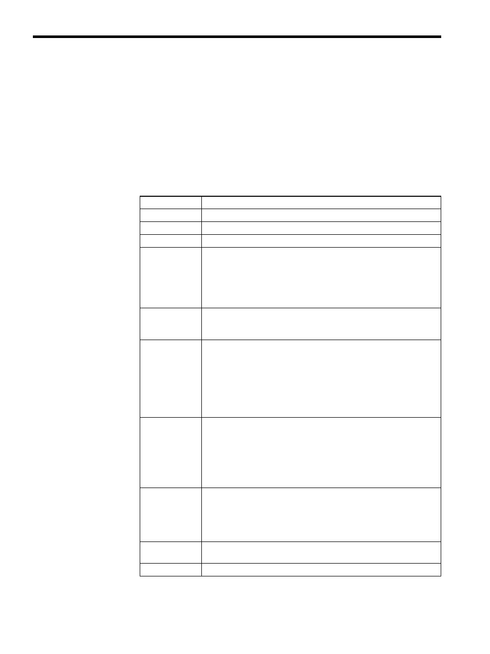
Table 5.1 shows the SVA-01A Module hardware specifications.
Table 5.1 SVA-01A Module Hardware Specifications
Item
Specifications
Name
4-axis Servo Module
Model Number
JEPMC-MC200A
Description
SVA-01A
Servo Interface
Pulse input circuit: 5 V differential, maximum 1 MHz input
(Maximum1.5 MHz input available for the hardware Ver.
3.5 or later.)
Pulse input method: A/B/C phase input (selected from 1
×, 2×, and 4×), A/B
mode, sign mode, Up/Down mode
Pulse counter latch: DI (select between zero point and external latch signal)
Analog Outputs
D/A speed references: Sign + 15 bits, 4 points
Output range: 0 to ±10 V
(Linearity guarantee range: Maximum output of 10 V or more)
Digital Inputs
Servo DI: 3 points
× 4 channels
4 mA at 24 VDC, source input
SV ALM, SRDY, BRK
External DI: 6 points
× 4 channels + general-purpose DI
4 mA at 24 VDC, source input
Axis unit: OTF, OTR, DEC, ZERO, EXT, RI
Common: RIC
(ZERO and EXT can be used as counter latch input signals.)
Digital Outputs
Servo DO: 6 points
× 4 channels, 24 VDC
SV ON, ALM RST, P_CON, SEN, OTR, OTF
External DO: 2 points
× 4 channels + general-purpose DO
24 VDC ±2%
Output current: 100 mA
Axis unit: BRK OUT
∗
, RO
Common: RCO
Connectors
CN1: Servo connector 1
10236-52A2JL
CN2: Servo connector 2
10236-52A2JL
CN3: Servo connector 3
10236-52A2JL
CN4: Servo connector 4
10236-52A2JL
CN5: External interface connector 10250-52A2JL
Indicators
Module status LED indicator
7-segment LED (green)
Dimensions
80
× 130 × 105 mm (W × H × D)