Yaskawa MP920 Motion Module User Manual
Page 209
5.4 SVA-01A and SVA-02A Parameters
5-67
5
2
RUN Refer-
ence Settings
(SVRUNCMD)
(cont’d)
Bit 14
Speed Reference
Type
(XREFTYPE)
Set the type of data for OL12 Position Reference Set-
ting when an OW20: Motion Command Code is used
in Position Control Mode.
0: Absolute position method
Sets the absolute position at OL12.
1: Incremental addition method
Adds the current movement value to the previous
value at OL12 and then sets that data at
OL12.
Note: Only the absolute position method can be set if
the position reference selection is indirectly
specified.
Refer to Position Reference of 2.3.1 Prerequisites for
Position Control.
1
Bit 15
Zero Point
Return Decelera-
tion Point Limit
Signal (LSDEC)
This bit functions as a limit switch signal (deceleration
LS) when returning to the zero point. It is valid when bit
2: Limit Switch Signal Selection is OFF at fixed parame-
ter number 14: Additional Function Selections. The
external signal (DI signal input by the LIO-01 or other
Module) in the user program must be connected (i.e., pro-
grammed) to OB01F.
0
3
Positive
Torque Limit
Setting
(TLIMP)
OW02
-32768 to 32767
Valid only for SVA-02A (2-axis) Module.
Used to set torque limit referenced by the SERVOPACK
and inverter.
Unit: 0.01%
Set a positive value (0.01% units) with a VS-866 and a
negative value (0.01% units) with a SERVOPACK.
-300.00
(-300.00
%)
4
Not used.
OW03
−
Set to “0.”
0
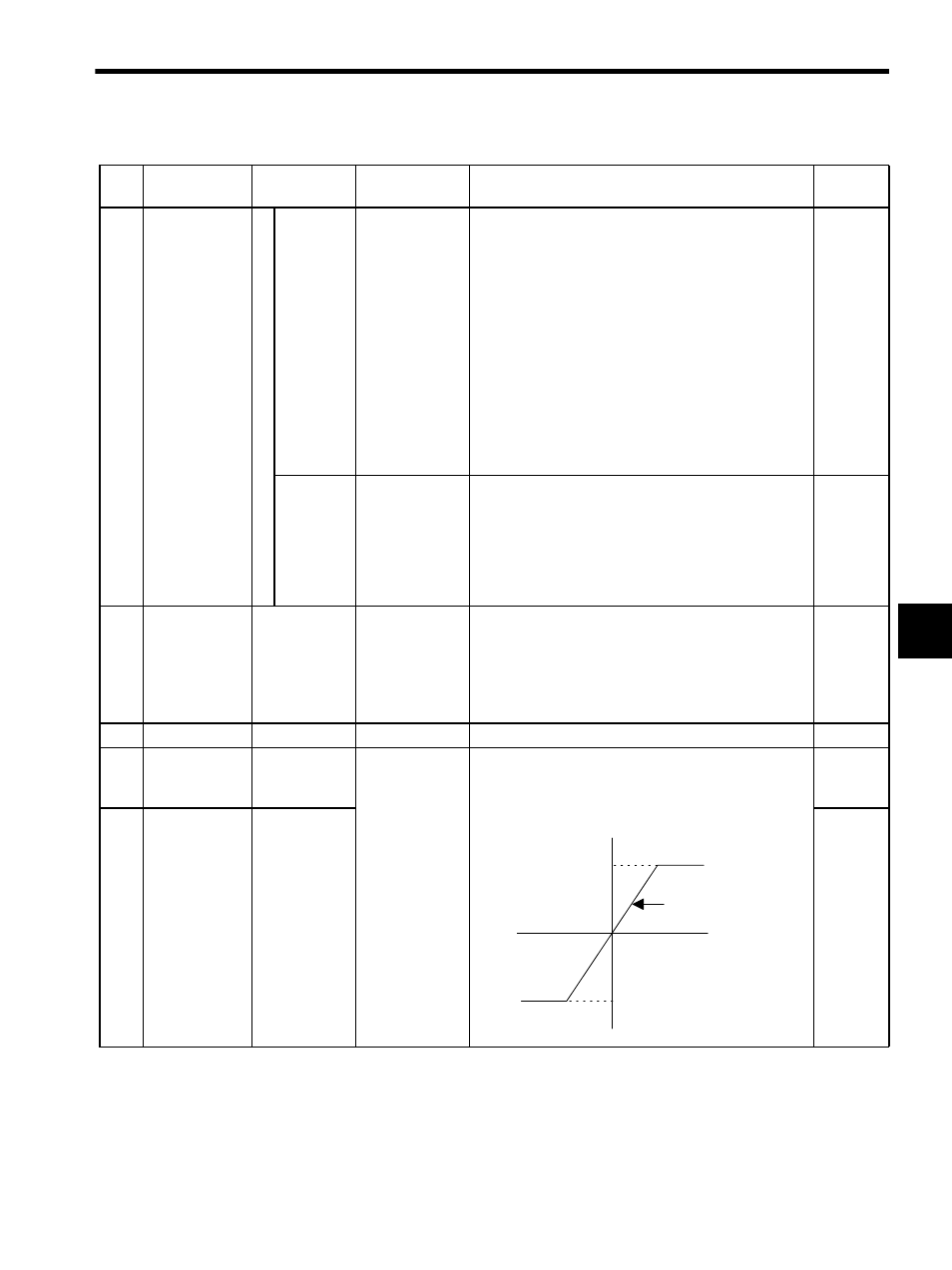
5
Positive Speed
Limiter Setting
(NLIMP)
OW04
0 to 32767
Set the speed limiter value for the positive and negative
directions as a percentage of the rated speed. The limiter
speed will be output if the compensation speeds added to
the specified speed exceeds this limiter value.
150.00
(150.00%)
6
Negative
Speed Limiter
Setting
(NLIMN)
OW05
150.00
(150.00%)
Table 5.6 Motion Setting Parameters (cont’d)
No.
Name
Register
Number
Setting Range/
Bit Name
Description
Factory
Setting
Positive speed limiter
Output speed
Negative speed limiter