Yaskawa MP920 Motion Module User Manual
Page 46
2 Motion Control
2.2.4 Phase Control Mode
2-20
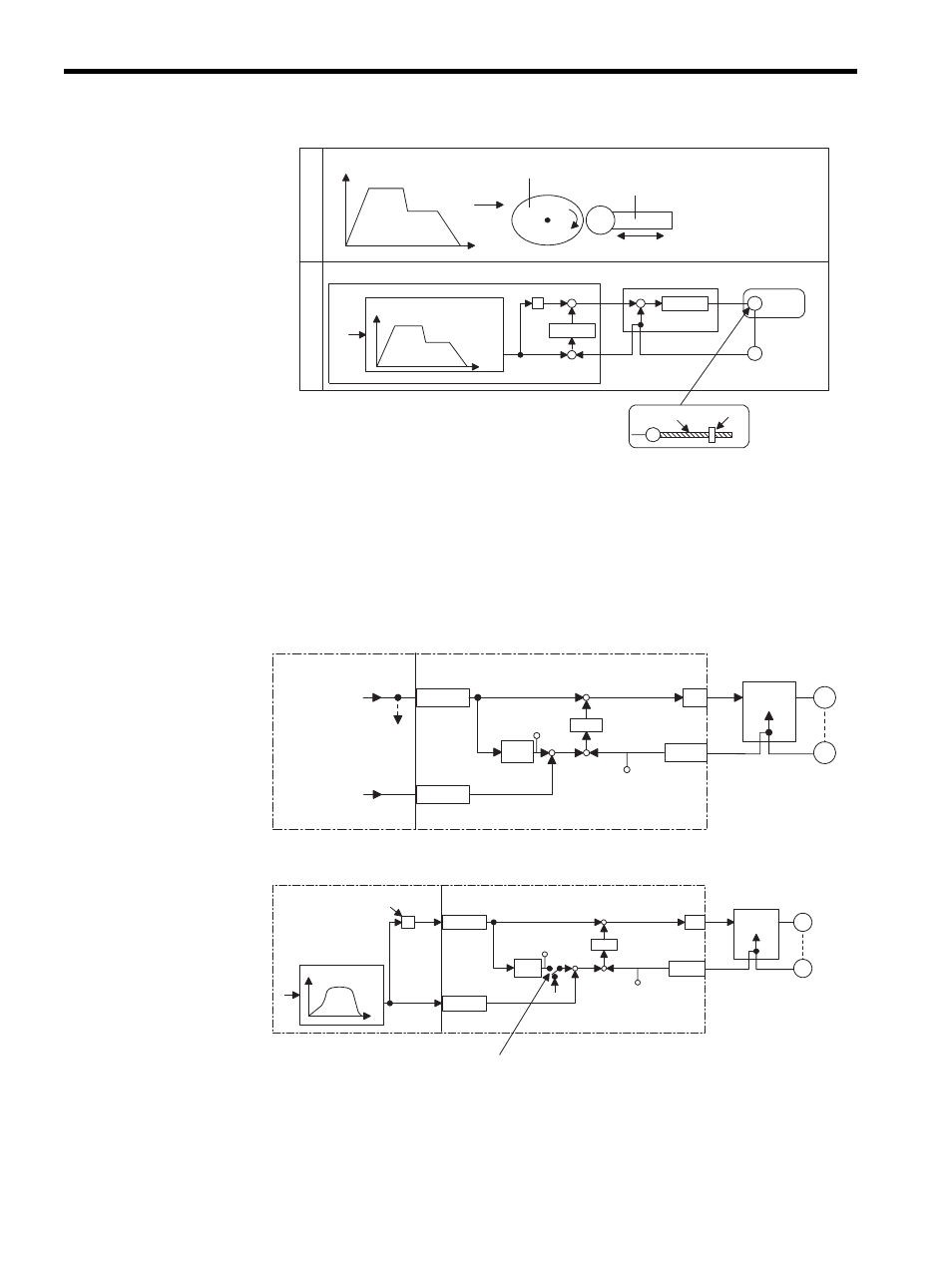
An electronic cam control loop can be configured using phase control. With normal phase
control, the position reference is generated by integrating the reference speed reference into
the SVA Module (see Fig. 2.8).
An electronic cam control loop cuts the integral circuit of the reference speed reference, and
provides the position reference from the phase compensation settings (see Fig. 2.9).
The following illustration shows a block diagram of a phase control loop.
Fig. 2.8 Block Diagram of Phase Control Loop
Fig. 2.9 Block Diagram of Electronic Cam Control Loop
The electronic cam control loop is processed in the SVA Module. Therefore, the user can
easily control the electronic cam simply by selecting the phase control mode on the CPU
Module and providing the required parameters for the SVA Module.
S
Xref
Servo
motor
+
+
+
-
+
-
M
PG
M
Mechanical cam
Electronic cam
Follower displacement
MP920
Follower displacement
Encoder
Ball screw Follower
Displacement pattern generation
Mechanical cam
Phase
θ
Phase
θ
Phase
refer-
ence
θ
Follower
When the mechanical
cam rotates, the follower
moves linearly, as shown
in the displacement
drawing.
Position control
Speed control
Speed
control
OWCO15
D/A
PI
Counter
OLCO16
NREF
SVA Module
To other
machine
CPU Module
Standard
speed
reference
setting
Position
compensation
setting
PHBIAS
M
PG
Servo driver
ε
+
-
+
+
±
Integra-
tion
APOS
IL
08
Speed
control
OWCO15
D/A
PI
Counter
OLCO16
NREF
SVA Module
When Phase Reference Generation Operation Disable
(bit 7 of OWC000) turns ON, the integral circuit is cut.
Position
reference
CPU Module
One scan change
calculation
Position reference
generation
PHBIAS
M
PG
Servo driver
ε
+ -
+
±
Integra-
tion
APOS
IL
08
S
θ
θ
×