Yaskawa MP920 Motion Module User Manual
Page 208
5 SVA Module Specifications and Handling
5.4.2 Motion Setting Parameters
5-66
Table 5.6 Motion Setting Parameters (cont’d)
No.
Name
Register
Number
Setting Range/
Bit Name
Description
Factory
Setting
2
RUN Com-
mand Settings
(SVRUNCMD)
(cont’d)
Bits 5 to 11 Not used.
Set to “0.”
0
Bit 12
Position Refer-
ence Value
Selection
(USE_BUF)
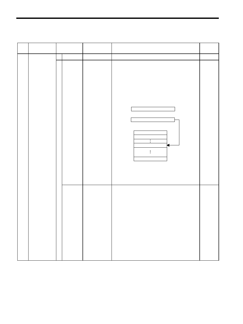
Set the reference method that is used for position refer-
ence data. It is valid only when an OW20: Motion
Command Code is used in Position Control Mode.
0: OL12
Use OL12 as directly as position reference data.
1: Position Buffer
Use OL12 indirectly as the position buffer num-
ber.
• The position buffer is located in the SVA Module and
must be written in the initial drawing at startup.
• Refer to OB21E, OB21F, and OL3A for
details on writing to the position buffer.
0
Bit 13
Speed Reference
Value Selection
(SPDTYPE)
Set speed reference method for feed speed, approach
speed, and creep speed. It is valid only when an
OW20: Motion Command Code is used in Position
Control Mode.
0: OL22
Set speed in reference units and sets rapid traverse
speed at OL22. The setting unit for OW0A:
Approach Speed and OW0B: Creep Speed are
also 1 = 10 reference units/min.
1: OW15
Set speed using a percentage and sets rapid traverse
speed at OW15. The setting unit for OW0A:
Approach Speed and OW0B: Creep Speed are
also 1 = 0.01%.
Refer to Speed reference of 2.3.1 Prerequisites for Posi-
tion Control.
0
OL
12
100
Directly
specified
Position buffer
Position reference data 1
Position reference data 100
2
256
Position reference
Position buffer pointer
Indirectly
specified