Yaskawa MP920 Motion Module User Manual
Page 205

5.4 SVA-01A and SVA-02A Parameters
5-63
5
b) Torque Reference Output Mode
If the RUN signal turns OFF, 0 is output immediately as the speed reference, OFF is
output for the RUN signal with the VS-866 and OFF is output as the servo ON signal
with the SERVOPACK.
Table 5.6 Motion Setting Parameters (cont’d)
No.
Name
Register Num-
ber
Setting Range/
Bit Name
Description
Factory
Setting
1
RUN Mode
Settings
(RUNMOD)
(cont’d)
Bit 5
Phase Control
Test Mode
(PHTEST)
Set whether the results of phase reference calculations
and PI control calculations are valid or not in Phase Con-
trol Mode.
0: Valid
1: Not valid
When Not Valid is selected, this parameter functions
much like the Speed Reference Output Mode with the Fil-
ter Time Constant and Acceleration/Deceleration Time
Constant set to 0.
0
Bit 6
Alarm Clear
(ACR)
The following monitoring parameters will be cleared
when this bit turns ON.
• IW00 RUN Status: Error Counter Over (bit 0) and
Motion Setting Parameter Setting Error (bit 1)
• Alarms (IL22)
0
Bit 7
Phase Reference
Disable
(PHREFOFF)
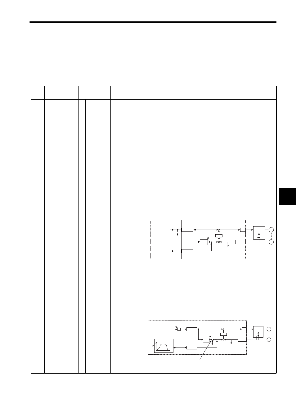
Set whether to use phase control for the electronic shaft
or electronic gear.
0: OFF (Electronic shaft)
1: ON (Electronic gear)
0
• Phase Control Loop (Electronic Shaft)
* 1. Integrates the standard speed reference and calculates the corre-
sponding position (pulse).
* 2. Generates a speed reference from the difference
ε between the tar-
get position (CPOS) and the current position (APOS). This is posi-
tion (phase) correction.
* 3. When shifting phase, the amount of shift (the rotating angle of the
Servomotor axis converted to pulses) is added as the phase correc-
tion setting.
• Electronic Cam Control Loop
OWCO15
D/A
Counter
PI
OLCO16
NREF
PHBIAS
M
PG
+
+
-
+
+
CPOS
IL
02
APOS
IL
08
SVA Module
CPU Module
Standard speed
reference setting
To other lines
Phase correction
setting
2
1
3
lnteg-
ration
Counter
Servo driver
Speed
control
∗
∗
∗
OWCO15
D/A
PI
OLCO16
NREF
PHBIAS
M
PG
+
+ -
CPOS
IL
02
APOS
Counter
IL
08
SVA Module
Servo driver
Speed
control
Integ-
ration
X
S
Position
reference
CPU Module
Calculated amount of
change per scan
Position reference
generated
θ
θ
Phase reference generation calculation disabled
The integration circuit is cut off when (bit 7 of OWC000)
turns ON.
