3 counter modes, 1 reversible counter mode – Yaskawa MP920 Motion Module User Manual
Page 423
10 CNTR-01 Module Specifications and Handling
10.3.1 Reversible Counter Mode
10-22
10.3 Counter Modes
This section explains the counter modes for the CNTR-01 Module.
10.3.1
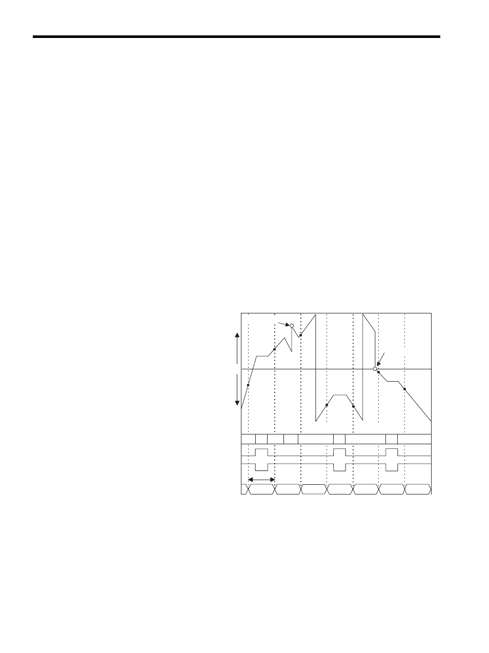
Reversible Counter Mode
The Reversible Counter Mode increments or decrements the count according to pulse A and
pulse B inputs. Counting is interrupted during pulse C input.
Note: Fixed parameter 11 can be used to stop or start counting for pulse C
inputs.
The following functions are possible in Reversible Counter Mode depending on output reg-
ister designations.
• Count Prohibited: Disables counting.
• Count Preset: Forcibly changes count values.
• PI Latch Detection: Writes the counter value to memory when an external signal is input.
• Coincidence Detection: Outputs an external output signal when the Set Coincidence
Detection output register value and the current counter value are the same.
* 1. Current counter value = Hardware counter (IL + 4)
* 2. Count preset = Count preset data (OL + 2)
n1
n2
n3
n4
n5
n6
n7
n1
n2
n3
n4
n5
n6
n7
MIN
(80000000H)
MIN
(80000000H)
UP
UP
DOWN
UP
DOWN
DOWN
Ts
0
(+)
(-)
Ts: Scan setting
MAX (7FFFFFFFH) MAX (7FFFFFFFH)
Count
preset
*2
Count
preset
*2
Count register
Pulse A and pulse B
Pulse C terminal (positive logic)
Pulse C terminal (negative logic)
Current counter value
*1
Stop
Stop
Stop