3 frequency measurement – Yaskawa MP920 Motion Module User Manual
Page 427
10 CNTR-01 Module Specifications and Handling
10.3.3 Frequency Measurement
10-26
10.3.3
Frequency Measurement
Frequency is measured according to pulse A and pulse B pulse trains. The detected fre-
quency is stored in the input register each scan. The current count is stored as the current
hardware counter value.
The following function is possible in Frequency Measurement Mode, depending on output
register designations.
• Coincidence Detection: Outputs an external output signal when the Set Coincidence
Detection output register value and the current counter value match.
* 1. Current counter value = Hardware counter (IL + 4)
* 2. Frequency = Average frequency (OL + 8)
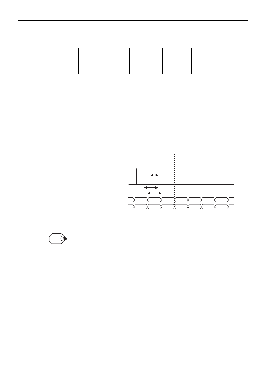
Frequency Measurement Principles
The frequency is calculated as follows:
•
Nn-1 and Nn: Current counter value for the input pulse for each high-speed or low-speed scan.
T:
Time between input pulses. Measurement unit: 8 MHz = 0.125
μs
MULT: Frequency coefficient set in the fixed parameter.
The above equation is used to calculate the frequency when there is one or more pulses input during
the measurement cycle. If, however, there is no pulse inputs, the calculation result will be a value esti-
mated from the previous frequency. True values are calculated for measurement cycles during which a
pulse has been input.
Table 10.7 Output Data
Name
Register No.
Range
Meaning
Operating Mode
OW
Each bit
−
Set Coincidence
Detection
OL + 4
0 to
± 2
31
-1
1 = 1 pulse
Nn-2
Nn-1
Nn
Nn+1
Nn+2
Nn+2
Nn+1
f2
f3
f4
f5
f7
f8
f6
f1
Ts
Nn-2
Nn-1
Nn
Nn+1
Nn+2
T
T
1
Input pulse
Current counter value
*1
Frequency
*2
INFO
F
Nn–Nn–1
T
MULT
×
=