Yaskawa MP920 Motion Module User Manual
Page 259
6 SVB Module Specifications and Handling
6.2.2 Motion Setting Parameters
6-24
Table 6.3 Motion Setting Parameters (cont’d)
No.
Name
Register
Number
Setting Range/
Bit Name
Description
Factory
Setting
2
RUN Com-
mand Settings
(SVRUNCMD)
OW01
Set the output signal from SVB-01 Modules to the driver as well as the RUN mode
required for motion control. The bit configuration is described below.
Bit 0
Servo ON
(DO0)
Used as the servo ON signal for the servo drive.
The servo command is sent to the servo drive when
SVCRDY (IB007) is set to ON and this bit is set to 1.
0: OFF, 1: ON
0
Bits 1 to 11 Not used.
Set to “0.”
0
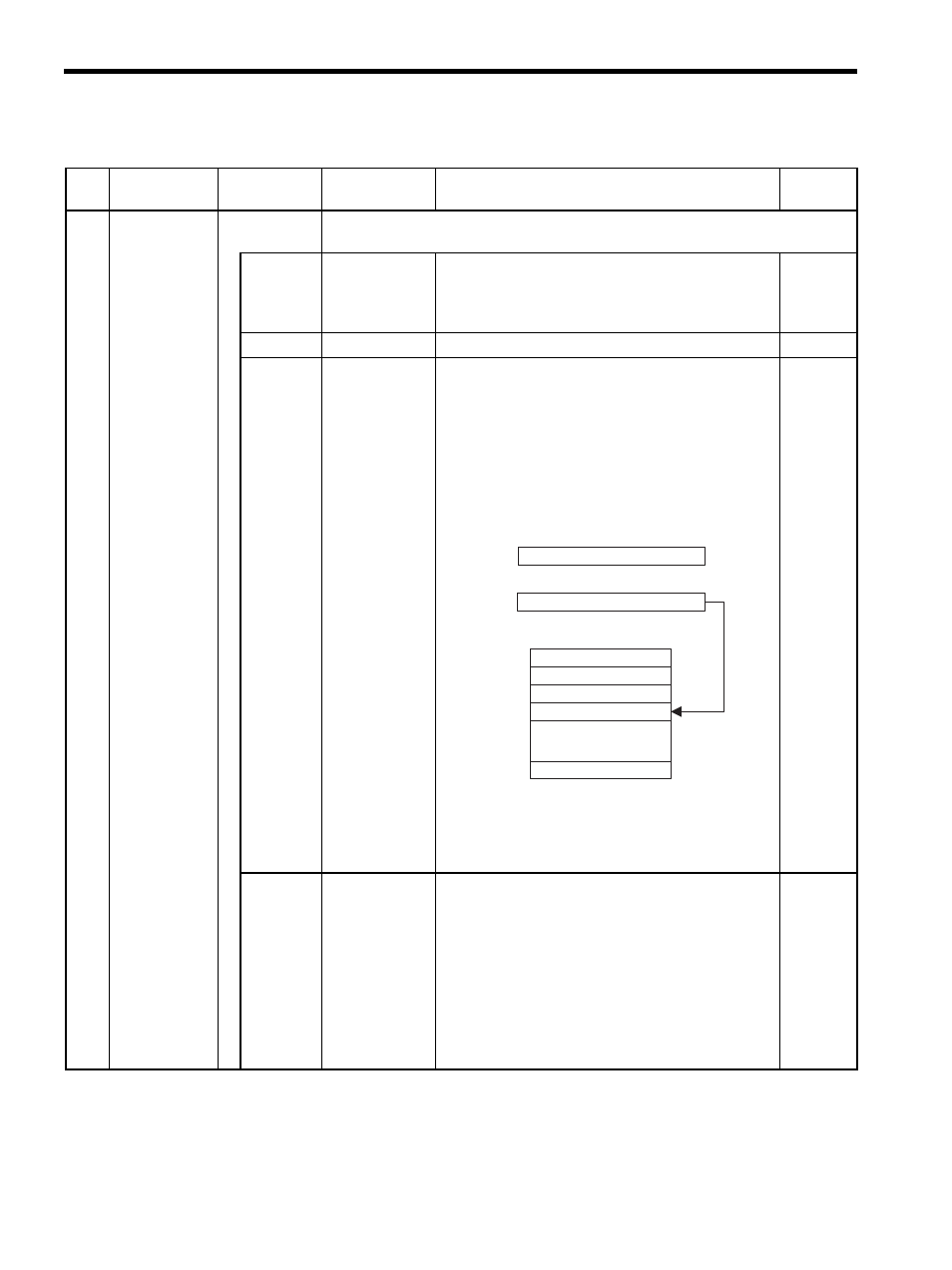
Bit 12
Position Refer-
ence Value
Selection
(USE_BUF)
Set the reference method that is used for position refer-
ence data. It is valid only when an OW20: Motion
Command Code is used in Position Control Mode.
0: OL12
Use OL12 as directly as position reference data.
1: Position Buffer
Use OL12 indirectly as the position buffer num-
ber.
• The position buffer is located in the SVB Modules and
must be written in the initial drawing at startup.
• Refer to OB21E, OB21F, and OL3A for
details on writing to the position buffer.
0
Bit 13
Speed Reference
Value Selection
(SPDTYPE)
Set the feed speed reference method. It is valid only when
an OW20: Motion Command Code is used in Posi-
tion Control Mode.
0: OL22
Set speed in reference units and sets rapid traverse
speed at OL22. The setting unit is 1 = 10
n
refer-
ence units/min.
1: OW15
Set speed using a percentage and sets rapid traverse
speed at OW15. The setting unit is 1 = 0.01%.
0
Position reference
OL
12
Position buffer
Position reference data 1
2
Position reference data 100
256
100
Directly
specified
Indirectly
specified
Position buffer pointer