3 differences between sva-01a and sva-02a modules, 1 differences in hardware – Yaskawa MP920 Motion Module User Manual
Page 185
5.3 Differences between SVA-01A and SVA-02A Modules
5-43
5
5.3
Differences between SVA-01A and SVA-02A Modules
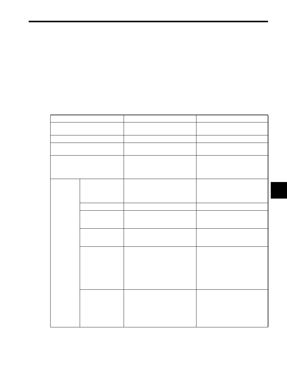
This section describes differences between the SVA-01A and SVA-02A Modules.
5.3.1
Differences in Hardware
The following table shows differences in hardware between the SVA-01A and SVA-02A
Modules.
Item
SVA-01A
SVA-02A
Number of Controlled Axes per
Module
4
2
Maximum Number of Modules
15
16
Maximum Number of Controlled
Axes
60
32
Control Functions
Speed reference output
Synchronized phase control
Position control
Speed reference output
Synchronized phase control
Position control
Torque reference output
Hardware
Specifica-
tions
Analog Outputs
Speed references:
PWM 16 bits
× 4 channels
Speed references:
PWM 16 bits
× 2 channels
Torque references:
D/A 12-bit references
× 2 channels
Analog Inputs
None
16 bits
× 2 channels
Pulse Inputs
A/B/C phase input
(selected from 1
×, 2×, and 4×),
A/B, sign, Up/Down
A/B/C phase input
(selected from 1
×, 2×, and 4×),
A/B, sign, Up/Down
Pulse Latch Digital
Inputs
Zero point latch input (ZERO) and
external latch input (EXT) can be
switched.
DI-5 (EXT)
General-purpose
Digital Inputs (Servo
Connectors)
3 points
× 4 channels
6 points
× 2 channels
• SV ALM
• SRDY
• BRK
• SV ALM
• SRDY
• BRK
• OTF (general-pur-
pose)
• OTR (general-pur-
pose)
• EXT latch (general-
purpose)
General-purpose
Digital Outputs (Ser-
vo Connectors)
6 points
× 4 channels
6 points
× 2 channels
• SV ON
• ALM RST
• PCON
• SEN
• STF
• STR
• SV ON
• ALM
RST
• PCON
• SEN
• OTF (general-pur-
pose)
• OTR (general-pur-
pose)