Yaskawa MP920 Motion Module User Manual
Page 231
5.4 SVA-01A and SVA-02A Parameters
5-89
5
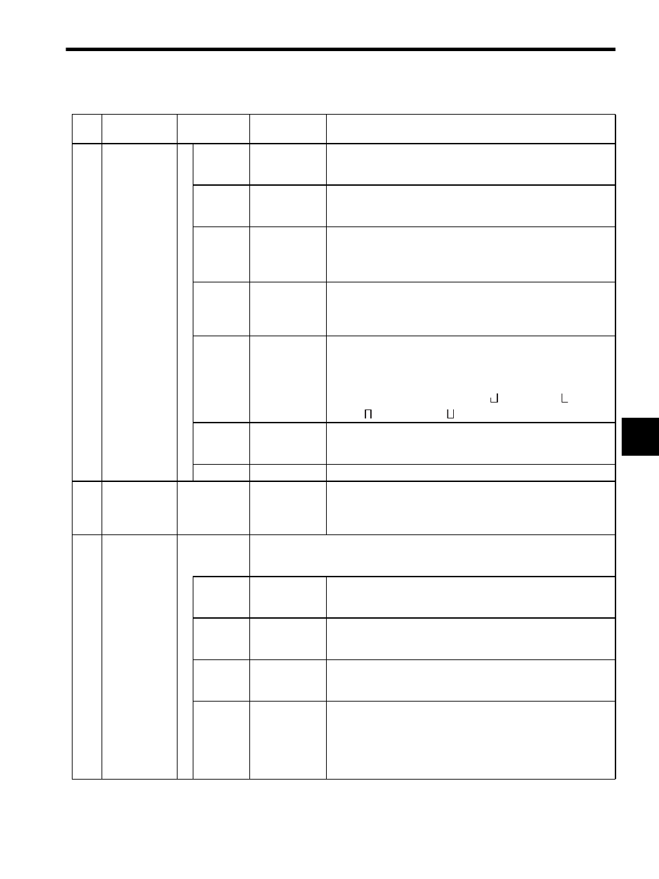
22
Motion Com-
mand Status
(MCMDSTS)
(cont’d)
Bit 1
Command Hold
Completed Flag
(HOLDL)
Turns ON when a HOLD is completed. Refer to individual motion
functions for details on the HOLD function.
Bit 2
Distribution
Completed
(DEN)
Turns ON when the amount of movement cleared is completed.
Bit 3
Zero Point Set-
ting Completed
(ZSET)
Turns ON when the zero point setting (ZSET) has been executed by
OW20: Motion Command Code.
It also turns ON when bit 3 of IW17: ABS System Infinite Length
Position Control Data Load Request has finished execution.
Bit 4
External Posi-
tioning Signal
Latched
(EX_LATCH)
Turns ON when the external positioning signal is input during external
positioning (EX_POSING).
Bit 5
Command Error
End (FAIL)
Turns ON if an alarm occurs while a movement (positioning, feeding,
etc.) command is being executed. Operation cannot continue once this
bit turns ON. Set Motion Command Code (OW20) to “NOP” for
one scan or more.
The SVA Module LEDs will indicate (
) (first axis), (
) (second
axis), (
) (third axis) or (
) (fourth axis) if this bit is ON.
Bit 6
Zero Point
Return Com-
pleted (ZRNC)
Turns ON when zero point return or zero point setting has been com-
pleted. Turns OFF when zero point return begins.
Bits 7 to 15 Not used.
−
23
Number of Dig-
its Below Deci-
mal Monitor
(DECNUMM)
IW16
0 to 5
Indicates motion fixed parameter No. 18: Number of Digits Below
Decimal Point. It is valid in Position Control Mode when an
OW20: Motion Command Code is used.
24
Position Con-
trol Status
(POSSTS)
IW17
Monitors status related to position controlled by SVA Modules.
It is valid in Position Control Mode when an OW20: Motion Command Code is used.
The bit configuration is described below.
Bit 0
Machine Lock
ON (MLKL)
Turns ON when machine lock is ON and analog signals will not be
output. The axis that is being controlled will be locked and will remain
stopped.
Bit 1
Zero Point Posi-
tion (ZERO)
Turns ON when zero point return (IB156) has been completed
and when 0
≤ |IL18: Reference Position in Machine Coordinate
System|
≤ OW83: Zero Point Position Output Width.
Bit 2
Second In-posi-
tion Completed
(PSET2)
Turns ON when Distribution Completed (IW15 bit 2) is ON and
when |IL08: Current Position
− IL18: Reference Position in
the Coordinate System|
≤ OW82: Second In-position Width.
Bit 3
ABS System
Infinite Length
Position Control
Data Load Com-
pleted
(ABSLDE)
Turns ON when OB2D2: ABS System Infinite Length Position
Control Data Load Request turns ON and the load has been com-
pleted. It turns OFF when OB2D2: ABS System Infinite Length
Position Control Data Load Request turns OFF.
It is valid when infinite length axis is set with an absolute encoder.
Table 5.7 Motion Monitoring Parameters (cont’d)
No.
Name
Register
Number
Setting Range/
Bit Name
Description