Programming example – Yaskawa MP920 Motion Module User Manual
Page 325
7.2 Functions
7-23
7
Programming Example
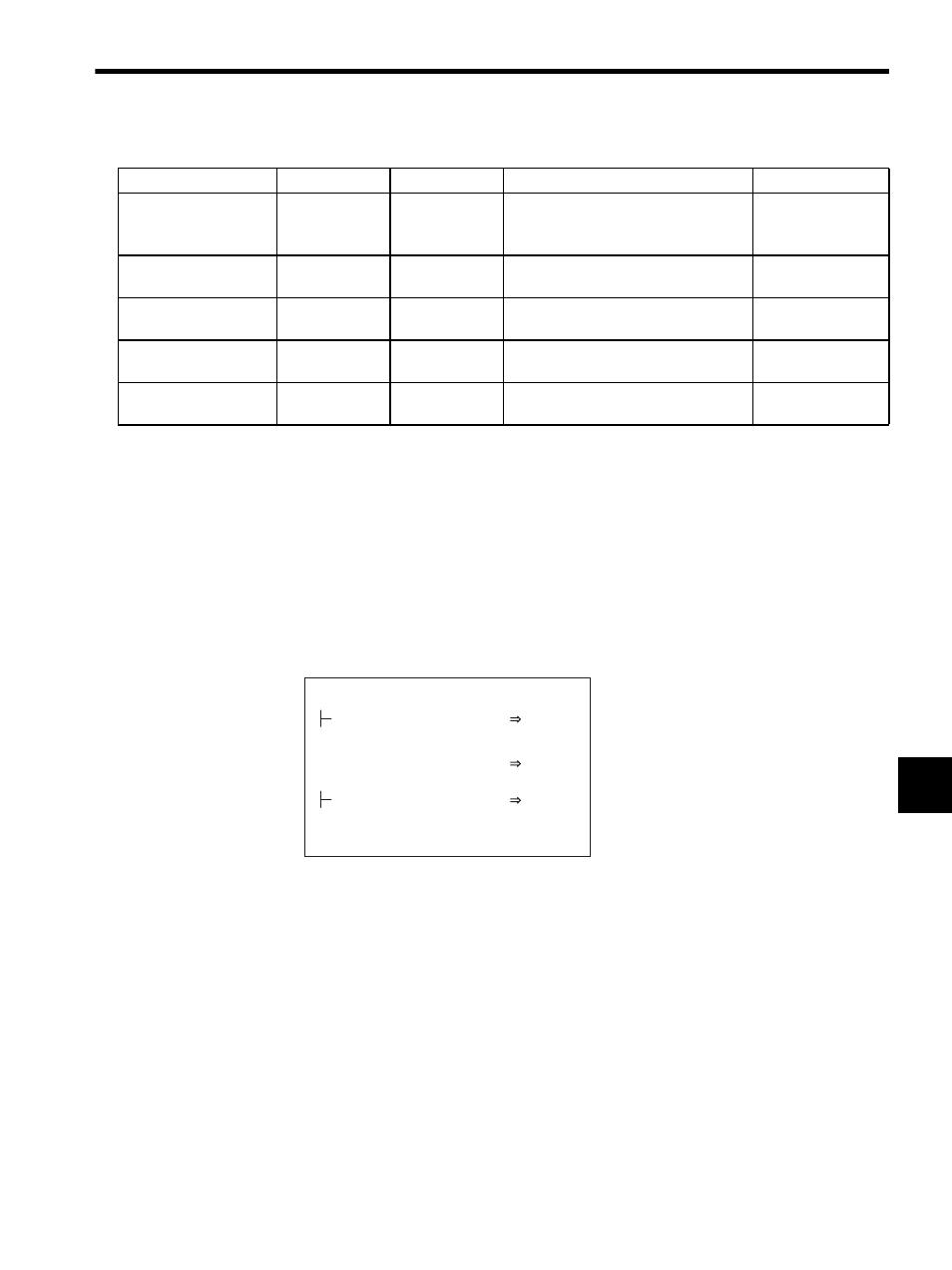
The user program shown in DWG.A was created to set the initial values shown in the figure
below. The initial values can also be entered on the Setup Parameters Tab Page from the
MPE720 and then saved to achieve the same settings. The initial values that are saved will
be set for motion parameters automatically when the MP920 is turned ON. The user pro-
gram created in DWG.A is thus only an alternate means of setting initial settings, and we
recommend using the Setup Parameters Tab from the MPE720 to set and save the parame-
ters to simplify making the initial settings.
Fig. 7.2 Initial Settings (DWG A01)
Table 7.7 Examples of Setting Parameter Settings
Name
Register No.
Setting Range
Meaning
Setting Example
RUN Mode Settings
OW00
−
Bit 2: Position Control Mode
Bit 8: Motion Command Code Enabled
Selection
104 H
Linear Acceleration
Time Constant
OW0C
0 to 32767
Acceleration time until the rated motor
speed is reached.
500 ms
Linear Deceleration
Time Constant
OW0D
0 to 32767
Deceleration time from the rated motor
speed until a speed of 0 is reached.
500 ms
Motion Command
Code
OW20
0 to 65535
Motion command 7 = Feed
7
Rapid Traverse Speed
OL22
0 to 2
31
-1
Distance moved using the FEED, STEP,
and POSING commands.
400000 pulse/min
DEND
Run Mode Settings (RUNMOD)
(Position Control Mode Selection, Motion Commancd
Code Enabled)
Linear Deceleration Time Constant (NDEC)
500
NACC
OWC00C
Linear Acceleration Time Constant (NACC)
NDEC
OWC00D
H104
RUNMOD
OWC000