Ladder logic program example – Yaskawa MP920 Motion Module User Manual
Page 45
2.2 Control Modes
2-19
2
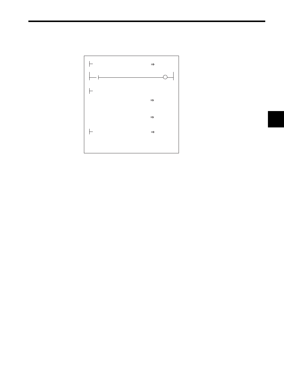
Ladder Logic Program Example
Fig. 2.7 RUN Commands (DWG H04)
The example in the above illustration has been greatly simplified. In actual operation, each
register can be controlled from the user program.
User Program Example 2: Electronic Cam
Example of RUN Operation
Cams are one of the conventional methods for changing a rotational movement to a linear
movement, and they are used to obtain the desired operation curve (displacement drawing)
during a cycle.
• A mechanical cam forms a cam with a shape corresponding to this displacement draw-
ing. Placing a follower on the circumference and rotating the cam enables the desired
linear operation to be obtained.
• An electronic cam holds the actual displacement drawing data in the controller as a posi-
tion pattern, and performs regular position control for the so-called continuous path
(CP) by changing the phase.
RUN
OBC0010
PREPARE
MB010010
MW01010
×
×
MW01020 + ML02012
VERF
GEAR1
AMARI
÷ MW01021
GEAR2
NREF
OWC015
MOD
00001
AMARI
ML02012
ML01012
PHBIAS
OLC016
ISO-HOSE
DEND
H0108
RUNMOD
OWC000
Set the phase control mode to ON.
Set Phase Reference Generation Operation
Disable to OFF.
Driver RUN command (RUN)
When MB01010 turns ON, phase control
starts.
Set the reference speed reference (NREF).
The speed reference is stored in advance in
MW01010. The gear ratios are stored in
advance in MW01020 and NW01021. If gears
are not required, "1" is stored in advance.
To move the phase, set the phase
compensation (OLC016). The distance to be
moved (the angle of rotation of the motor axis
converted to the number of pulses) is stored in
advance in ML01012.