Inputs and outputs, Overview, Vav/zone controller analog inputs – WattMaster WM-WCC3-TGD-01B User Manual
Page 812: Other controller connections
The following inputs and outputs are available on the VAV/Zone
Controller and the OE325-01 Zone Controller Expansion Module. For
component locations of the inputs on the VAV/Zone Controller and VAV
Zone Controller Expansion Module see Figures 3, 4, and 6. For wiring
of inputs and outputs, see Figures 7 through 13.
VAV/Zone Controller Analog Inputs
Space Temperature
The Modular Room Sensor that reads space temperature is attached to
this input. The Modular Sensor connects via a modular cable to the VAV/
Zone Controller Actuator Package.
Airfl ow Sensor
If the OE744-32-VAVF VAV/Zone Controller Actuator Package is being
used, the terminal unit’s pressure pick-up tube must be connected with
FRP tubing to the barb fi ttings on the side of the enclosure. This pressure
sensor input is used for CFM (airfl ow) calculations. If an Airfl ow Sensor
is attached to this input, the VAV/Zone Controller can be programmed
for pressure independent operation.
NOTE:
VAV/Zone Controllers will automatically operate as Pres-
sure Independent if the Box Size Constant is greater
than 0 CFM.
Discharge/Duct Temperature Sensor
A Discharge/Duct Air Temperature Sensor can be connected to these
terminals. It should be mounted in the supply duct close to the terminal
unit where the VAV/Zone Controller is installed. This sensor can be
used for monitoring purposes in place of the Supply Air Temperature
Broadcast from the MCD; otherwise, the Discharge Air Temperature
will always read the same as the Supply Air Temperature.
NOTE:
1). All temperature sensors must be Thermistor Type
III which provide 77.0 ºF @ 10K Ohms Resistance.
2). The Supply Air Temperature Broadcast from the
MCD must be in a XXX.X format, one decimal place.
Other Controller Connections
Expansion Board Modular Connector
This modular connector is used to connect the optional OE325-01 Zone
Controller Expansion Module to the VAV/Zone Controller Actuator
Package. This module is only required when electric or hot water heat-
ing and/or fan terminal control is required. The Expansion Module is
not required for cooling only terminal units.
Actuator Modular Connector
This modular connector is used to connect a modular cable from the
VAV/Zone Controller to a tri-state actuator.
24 VAC Power Terminal Block
This two pole terminal block is used to wire the 24 Volt power to the
VAV/Zone Controller Actuator Packages If desired a single transformer
can be used to power multiple VAV/Zone Controller Actuator Packages
together, or a separate transformer can be used for each controller.
Warning: If multiple controllers are to be wired to the same
transformer, polarity must be observed or damage
to the controller will result.
Communications Terminal Block
This three pole terminal block is used for connecting the communications
wiring between each VAV/Zone Controller Actuator Package, Satellite,
Power/Comm board, or other controller on the local communications
loop. Communications wiring should be 18 gauge 2 conductor twisted
pair with shield, Belden #82760 or its equivalent.
OE325-01 Zone Controller Expansion
Module
As previously stated, when control of a fan or if heating is required, the
OE325-01 Zone Controller Expansion Module is required.
Relay Output #1 - Fan Enable
The fi rst expansion relay on the Output Expansion boards is used for
energizing the fan on Series or Parallel Fan Terminal Units.
Relay Output #2 - Heating Stage 1
If you have at least one stage of heating, this is the relay used to energize
the 1st stage of terminal unit heating. This heating stage can either be
used with electric heat or On/Off hot water valve control. For 3 stage
heating, this relay output would be energized for the 1st and 3rd stage of
heat. See the following section for more information regarding 3 stage
heating applications.
Relay Output #3 - Heating Stage 2
If you have two stages of electric heating, this relay controls the 2nd stage
of electric heat. For 3 stage heating, this relay output would be energized
for both the 2nd and 3rd stage of heat. See the following paragraph for
more information regarding 3 stage heating applications.
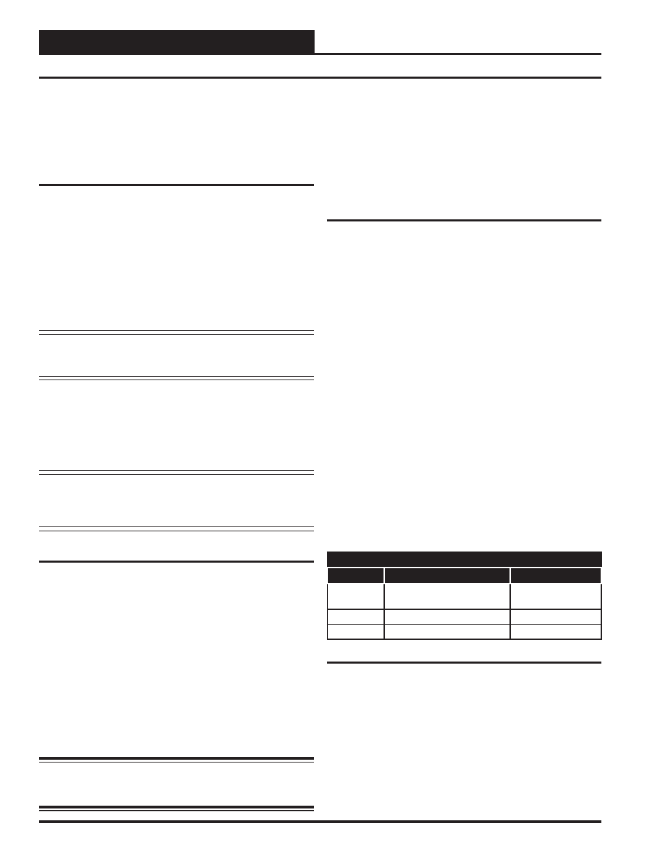
3 Stage Heating Applications
If three stages of electric heat are confi gured, relays #2 and #3 will stage
in a staggered sequence. This allows you to achieve 3 stages of heating
using only relays #2 and #3. Each of the 3 heating elements should be
sized for one third of the total KW output required. Both the 2nd and 3rd
stage heating contactors ( C2 & C3) must be connected to Relay Output
#3. See Table 1 below for relay sequencing information.
Relay Staging
Stage No.
Relay Output #2
Relay Output #3
1
VAV/Zone Controller
Package ON ( C1)
OFF (C2 & C3)
2
OFF (C1)
ON (C2 & C3)
3
ON (C1)
ON (C2 & C3)
Table 1: Relay Sequencing For 3 Stage Heating
Relay Output #4 - Not Used
Relay Output #4 is not currently being used
Analog Output
If you are using hot water or steam heating via a modulating steam
or hot water valve, this output can supply a 0-10 Volts DC signal for
proportional control of the valve.
Inputs and Outputs
8
VAV/Zone Controller Actuator Package Technical Guide
Overview