Controller inputs and outputs – WattMaster WM-WCC3-TGD-01B User Manual
Page 775
Operator Interface
VAV/Zone Controller Technical Guide
7
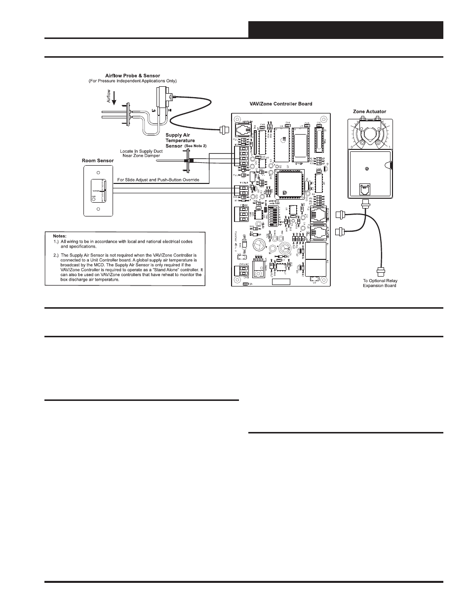
Figure 4: VAV/Zone Controller Wiring
Controller Installation & Wiring
Correct wiring of the VAV/Zone Controller is the most important factor
in the overall success of the controller installation process. The VAV/
Zone Controller wiring has been simplifi ed by the use of modular con-
nectors and prefabricated modular cables.
Controller Mounting
If the Round Zone Dampers or Rectangular Zone Damper Kits were
purchased from WattMaster, the controller and actuator are factory
mounted and wired in the damper control enclosure. If your VAV/Zone
Controllers are pressure independent, an airfl ow probe and pressure
sensor will also be factory mounted and wired.
Most terminal unit manufacturers will offer the option of factory mount-
ing the WCC III controls in their terminal units for an additional charge.
An installation worksheet and instructions are available for the VAV/
Zone Controller package which can be shipped with the VAV/Zone
control(s) to the terminal unit manufacturer to simplify third party fac-
tory mounting and wiring of the controller.
When the VAV/Zone Controller is to be fi eld mounted, it is important
to mount the controller in a location that is free from extreme high or
low temperatures, moisture, dust, and dirt. The VAV/Zone Controller
board must be mounted within 10” of the damper actuator in order for
the actuator cable to extend between the controller and the actuator.
Be careful not to damage the electronic components when mounting
the controller. Remove the controller from its snap track mount. Mark
the control enclosure base using the snap track as a template. Drill pilot
holes in the enclosure base and secure the snap track to it using sheet
metal screws. Do not allow metal shavings to fall onto the circuit board.
Reattach the controller to the snap track. Mount the damper actuator to
the damper shaft following the instructions supplied with the damper
actuator.
Important Wiring Considerations
Please carefully read and apply the following information when wir-
ing the VAV/Zone Controller. See Figure 4 for VAV/Zone Controller
wiring diagram.
1. Size and wire the transformer per the instructions. Failure to
size the transformer correctly may cause the VAV/Zone
controllers to operate erratically or not at all. See Figure 5
for wiring and transformer sizing information.
2. If a Discharge/Duct Air Sensor is to be connected, the mini-
mum wire size used should be 24 gauge.
3. Do not pry on the connectors when connecting or discon-
necting the terminals.
4. Communications wiring should be 18 gauge 2 conductor
twisted pair with shield, Belden #82760 or its equivalent.
This type of wire is available from WattMaster.
Controller Inputs and Outputs