To-20 milli-amp current sensors – WattMaster WM-WCC3-TGD-01B User Manual
Page 542
WCC III Technical Guide
12-46
12. WCC III INSTALLATION
4-to-20 Milli-Amp Current Sensors
The connection of a 4-to-20 milli-amp sensor to a SAT III controller
will require simple math to determine the “Zero” point of the 4-to-
20 milli-amp sensor. This is because the “Zero” point of the 4-to-
20 milli-amp sensor is actually not at zero volts. This “Zero” point
is actually at the 4 milli-amp point.
Various sensors that provide a 4-to-20 mA current output signal
can be used with the SAT III controllers. The SAT III controllers
are designed to work with a 4-to-20 milli-amp sensor to have
either a +1VDC selected input scaling range or +5VDC selected
input scaling range. The current that is measured across the load
resistor(s) on the SAT III input at full scale (20mA) on either of
the two input scaling range determines the load resistance value.
Since the SAT III load resistor(s) will have at most a 20 milli-amp
current going through them at full scale, and when the maximum
input voltage of either +1VDC or + 5VDC that is required across
the SAT III load resistor at 20 milli-amp. Therefore, when doing
the required math at +1VDC input scaling range, a 4-20 mA sensor
will require a 50 Ohm load resistor, and at a +5VDC input scaling
range, a 4-20 mA sensor will require a 250 Ohm load resistor.
V
1 Volt
R = --------- = ------------ = 50 Ohms
I 0.020 Amps
V
5 Volts
R = --------- = ------------ = 250 Ohms
I 0.020 Amps
Both values of load resistors - the 50 Ohm (Actually 49.9 Ohm) &
250 Ohm are provided in the resistor pack kit that is provided with
each new SAT III controller. The WattMaster part number of this
kit is PL102029.
When programming the WCC III Analog Input Screen for a 4-20
mA sensor, the 100% scale value is the value represented when the
sensor sends 20 mA to the SAT III controller, and the zero percent
scale value is the value represented when the sensor sends 0 mA
to the SAT III controller. For example, consider a 4-20 mA sensor
which measures duct static pressure. The sensor provides 4 mA
when the duct static pressure is 0 inches of water column and 20
mA when the duct pressure is 2 inches of water column. The 100
percent scale value on the Analog Input Screen is 2.00” W.C., and
the zero percent scale value is -0.50” W.C.
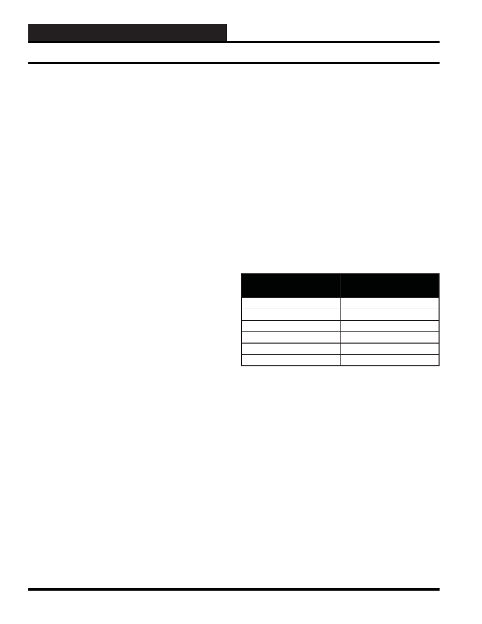
The full scale value is fairly straightforward and very easy to
understand. The zero percent scale value, on the other hand, is a bit
more complicated. The following table shows the signal out of the
sensor versus the duct static pressure.
Signal From Sensor
(mA)
Duct Static Pressure
20
2.00” W.C.
16
1.50” W.C.
12
1.00” W.C.
8
0.50” W.C.
4
0.00” W.C.
0
-0.50” W.C.
Figure 12-37: Analog Input Values
4-to-20 Milli-Amp Current Sensors