Sat iii, General instructions, Binary outputs – WattMaster WM-WCC3-TGD-01B User Manual
Page 61: Wcc iii technical guide 1-7
1. GENERAL INSTRUCTIONS
WCC III Technical Guide
1-7
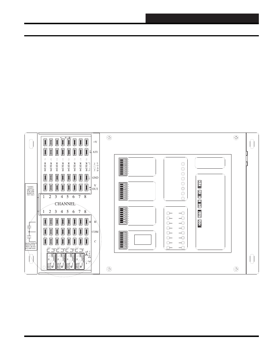
Binary Outputs
A binary output on the SAT III controller is the electronic equivalent
of a relay contact which is used to complete a circuit to activate
on/off devices such as relays, 2-position valves, etc. The binary
output contacts can be used to complete a 24 volt DC circuit or
24 volt AC circuit at 1.0 amp maximum load. The binary output
terminals are labeled H, COM, and C.
The SAT III controller is capable of providing 16 binary (on/off)
outputs.
The terminals for the binary outputs are found at the lower left hand
corner of the SAT III controller. The “COM” to “H” contacts are
referred to as K1h-K8h. The “COM” to “C” contacts are referred
to as K1c-K8c.
The SAT III can also accept up to three WCC III V-Out Relay
Boards.
8
7
SAT ADDRESS
2
1
4
8
A 3 WIRE ROOM SENSOR WILL NOT
REQUIRE A LOAD RESISTOR WHEN SET
FOR A 1 VOLT INPUT.
WattMaster Controls Inc.
BINARY
INPUTS
BINARY
INPUTS
L8
ON OFF
128
32
16
64
L4
L3
L2
L1
L6
L5
L7
L11
L12
ON OFF
L10
L9
ON OFF
L15
L16
L14
L13
C
H
4
3
5
6
2
1
LOCAL SET
STATUS 2
STATUS 3
STATUS 1
HSS XMIT
LOCAL SET
LOCAL SET DISABLE
BATT ON/ OFF
PULSE INPUT
OPTION 1
TEST
OPTION 3
OPTION 2
ON OFF
STATUS
HSS REC
SAT XMIT
SAT REC
ANALOG INPUT
JUMPER SELECTION
A 2 WIRE ROOM SENSOR WILL REQUIRE
A 300 OHM LOAD RESISTOR WHEN SET
FOR A 1 VOLT INPUT.
A 4 TO 20 mA SENSOR WILL REQUIRE A
50 OHM LOAD RESISTOR WHEN SET FOR
A 1 VOLT INPUT, OR A 250 OHM LOAD
RESISTOR WHEN SET FOR A 5 VOLT INPUT.
CURRENT
INPUT
THERMISTOR
INPUT
0 - 1V
0 - 5V
0 - 10V
THERM
0 - 1V
0 - 5V
0 - 10V
THERM
0 TO 10V
INPUT
0 TO 5V
INPUT
0 TO 1V
INPUT
0 - 10V
0 - 1V
0 - 5V
0 - 10V
THERM
0 - 1V
0 - 5V
THERM
0 - 1V
0 - 5V
0 - 10V
THERM
PROGRAMMABLE CONTROLLER
SAT III
Binary Outputs