I. introduction, Accessory boards - power and switchable comm – WattMaster WM-WCC3-TGD-01B User Manual
Page 40
I. INTRODUCTION
WCC III Technical Guide
I-18
Accessory Boards - Power and Switchable Comm
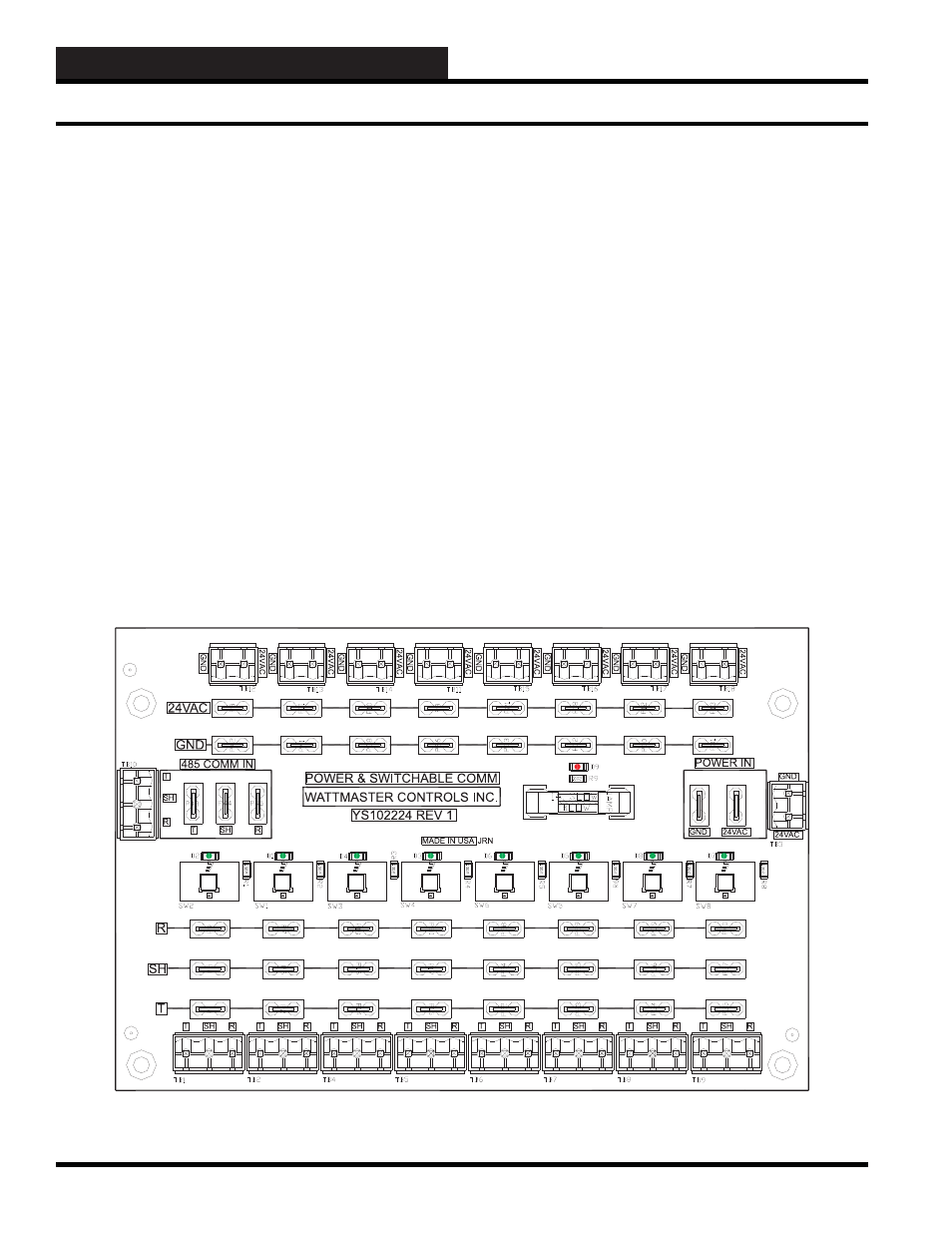
Power and Switchable Comm Board
The Power and Switchable Comm Board was designed to be used as
a central connection point for the SAT III RS-485 communications
loop.
Eight push-button switches are provided to disconnect the RS-485
communications loop for troubleshooting purposes.
The RS-485 communication connections are as follows: “R”
to “R”, “T” to “T”, and “SHLD” to “SHLD” or “SH”. These
connections are from Satellite-type controller to Satellite-type
controller. These eight push-button switches only disconnect
the RS-485 communications loop. THEY DO NOT SWITCH
POWER ON/OFF. See Section 19 for specifi c use and application
of the WCC III Power and Switchable Comm Board.
This Power and Switchable Comm Board may also be used as a
central connection point for the SAT 3C/D/F TUC communications
loop.
Figure I-14: The Power and Switchable Comm Board
The RS-485 communication connections are as follows: “R” to
“R”, “T” to “T”, and “SHLD” to “SHLD” or “SH”. This RS-
485 communications connection is from TUC Controller to TUC
Controller. But, on the SAT 3C/D/F Controller, the TUC “R”
connection must be wired to the SAT 3C/D/F “T” connection, and
the SAT 3C/D/F Controller “R” connection must be wired to the
TUC “T” connection. This is a carry over connection method from
the old SAT 2C/D Controller.
The WCC III Power and Switchable Comm Board has 9 status
lights. The functions of these lights or LEDs are listed below:
•
D9
- This LED will be lit any time power is applied to
the WCC III Power and Switchable Comm Board.
•
SW1 to SW8
- These eight LEDs will be lit any time a
corresponding push button is depressed to connect the
RS-485 communications to the corresponding eight
communication ports.