WattMaster WM-WCC3-TGD-01B User Manual
Page 526
WCC III Technical Guide
12-30
12. WCC III INSTALLATION
WCC III Binary Input with Time Delay
Board – Connection Points (SS5006)
All external WCC III Binary Input with Time Delay board
connection points are de-pluggable screw-cage type of wire
clamped based terminal blocks. With the exception of the “old”
connection method of connecting the Binary Inputs which are a
16-pin dip cable connection, and the HSS EXP COMM port which
is a 6-pin pre-made MOLEX type mini-fi t cable connection.
HSS Connectors (P2 & P3
Communications)
There are two of these 6-pin Mini-fi t connectors, and each of these
connectors could provide power and communications to and from
the WCC III Binary Input with Time Delay board to the SAT III
controller. These connectors are generally called HSS ports. The
WCC III Binary Input with Time Delay board requires 24 VAC
and ground connections which are then connected into these
connector terminals. The WCC III Binary Input with Time Delay
board is generally powered by the same 24 VAC transformer that
powers the satellite controller. Communications to the SAT III
controller is also in this cable, along with a shield wire. The 6-pin
HSS cable connections can also be daisy chained to other WCC III
Binary Inputs with Time Delay boards and WCC III V-Out relay
boards.
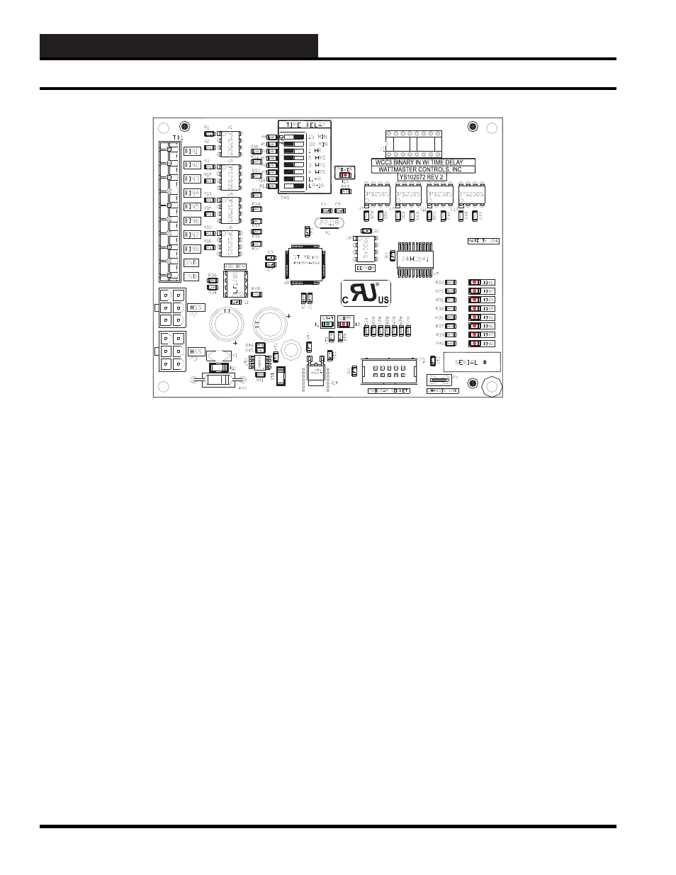
Figure 12-25: The WCC III Binary Input with Time Delay board
Contact Inputs 1 to 8 and GND
When the contact is closed between one of eight inputs of the contact
inputs connector and ground it will activate one of the eight LEDs
and makes a simulated contact closure on the J1 connector. This J1
connector is then connected via a 16-pin ribbon cable to one of the
SAT III controller’s former Binary Input dipswitch locations. This
input is automatically kept on for a timed duration depending on
the value of the dipswitch that is located on the WCC III Binary
Input with Time Delay board. As an alternative connection method
the HSS connection between the SAT III controller and the WCC
III Binary Input with Time Delay board delay board has the ability
to instantaneously notify the SAT III controller that an Input has
changed. And, from within the SAT III Binary Input screen, the
individual time duration for each and every binary input could be
set differently.
J1
(Socket connection to one of the SAT III
Binary Input former dipswitch locations)
This connector is polarized, and must be properly inserted at both
ends. Pin #1 of the J1 socket must mate with Pin #1 of one of
the SAT III former dipswitch locations. (The dipswitch on the
SAT III must be removed) If using the HSS connection method,
this connection to the SAT III controller does not need to be
connected.
WCC III Binary Input with Time Delay Board Connection Points