Sat iii, Sat iii led descriptions, Wcc iii technical guide 12-16 – WattMaster WM-WCC3-TGD-01B User Manual
Page 512: Led blinks every 1 second if sat iii is alive, Sat rec, Sat xmit, Hss rec, Hss xmit, Local set, Status 1

WCC III Technical Guide
12-16
12. WCC III INSTALLATION
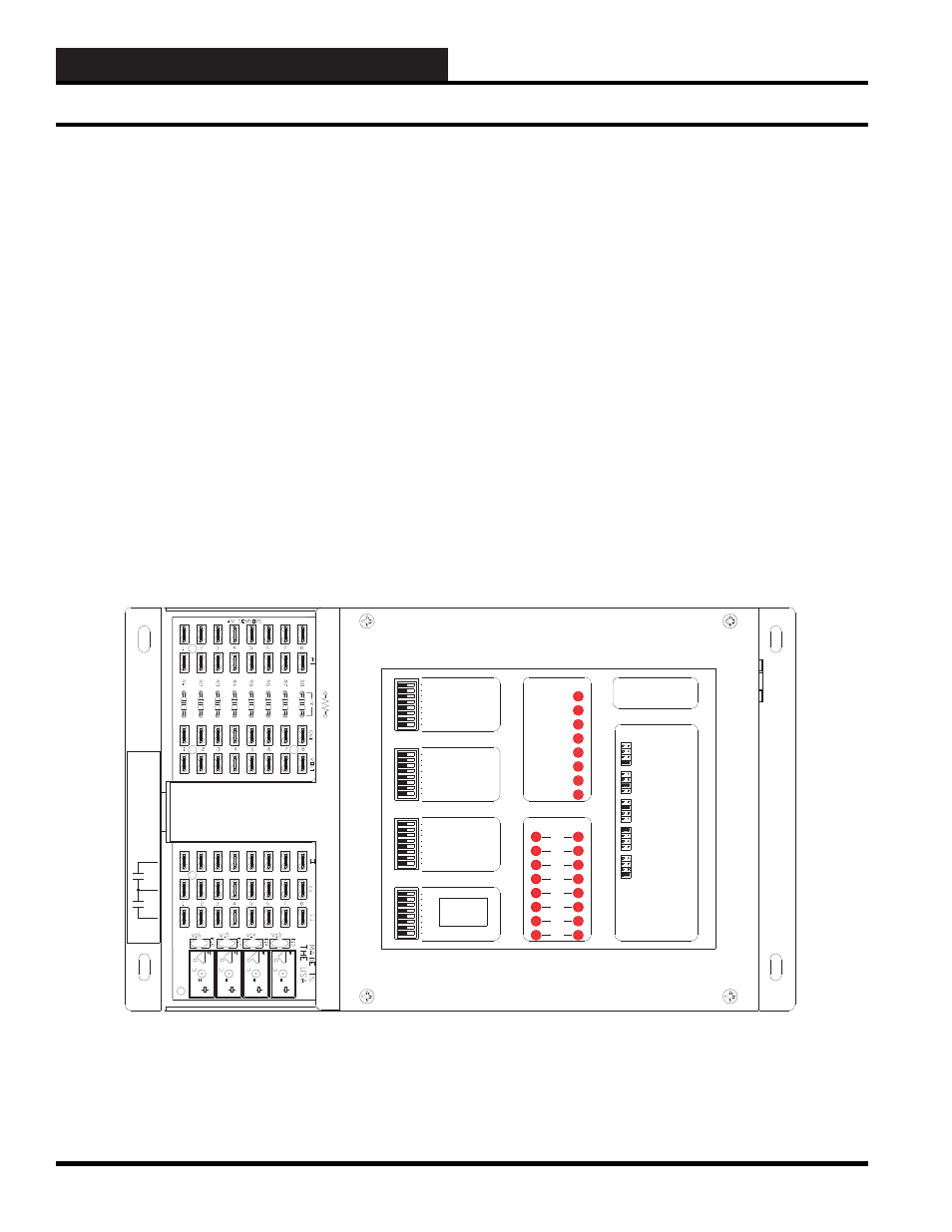
SAT III Controller—LED Information
(SS5003)
The SAT III Controller has 24 LEDs on the cover of the SAT III
controller. The top 8 Status LED functions are as follows:
SAT REC
- This LED will be lit when communications are being
received by the SAT III Communications Loop.
SAT XMIT
- This LED will be lit when communications are being
transmitted by the SAT III Communications Loop.
HSS REC
- This LED will be lit when communications are being
received from the HSS port.
HSS XMIT
- This LED will be lit when communications are
being transmitted to the HSS port.
LOCAL SET
- This LED will be lit when communications
with the WCC III-MCD has not occurred for at least the last two
minutes. This means that the SAT III is not communicating on the
SAT III communications loop. Setpoint control in the SAT III is
dependent on the LOCAL SET parameters which are programmed
into each control point by the user.
STATUS 1
- LED blinks every 1 second if SAT III is alive.
STATUS 2
- LED blinks every 1 second during power on delay,
and then blinks every 8 seconds when watchdog is enabled.
STATUS 3
- LED blinks for every internal calculation loop
completion.
The lower 16 LEDs display the status of the 16 “H” and “C” Relay
Outputs. The 16 LEDs display the status of the eight “H” and eight
“C” contacts.
8
7
SAT ADDRESS
2
1
4
8
A 3 WIRE ROOM SENSOR WILL NOT
REQUIRE A LOAD RESISTOR WHEN SET
FOR A 1 VOLT INPUT.
WattMaster Controls Inc.
BINARY
INPUTS
BINARY
INPUTS
L8
ON OFF
128
32
16
64
L4
L3
L2
L1
L6
L5
L7
L11
L12
ON OFF
L10
L9
ON OFF
L15
L16
L14
L13
C
H
4
3
5
6
2
1
LOCAL SET
STATUS 2
STATUS 3
STATUS 1
HSS XMIT
LOCAL SET
LOCAL SET DISABLE
BATT ON/ OFF
PULSE INPUT
OPTION 1
TEST
OPTION 3
OPTION 2
ON OFF
STATUS
HSS REC
SAT XMIT
SAT REC
ANALOG INPUT
JUMPER SELECTION
A 2 WIRE ROOM SENSOR WILL REQUIRE
A 300 OHM LOAD RESISTOR WHEN SET
FOR A 1 VOLT INPUT.
A 4 TO 20 mA SENSOR WILL REQUIRE A
50 OHM LOAD RESISTOR WHEN SET FOR
A 1 VOLT INPUT, OR A 250 OHM LOAD
RESISTOR WHEN SET FOR A 5 VOLT INPUT.
CURRENT
INPUT
THERMISTOR
INPUT
0 - 1V
0 - 5V
0 - 10V
THERM
0 - 1V
0 - 5V
0 - 10V
THERM
0 TO 10V
INPUT
0 TO 5V
INPUT
0 TO 1V
INPUT
0 - 10V
0 - 1V
0 - 5V
0 - 10V
THERM
0 - 1V
0 - 5V
THERM
0 - 1V
0 - 5V
0 - 10V
THERM
PROGRAMMABLE CONTROLLER
SAT III
H
C
COM
CHANNEL
2
1
3 4
2
1
3 4
5 6 7 8
5 6 7 8
V
OUT
GND
L
O
A
D
+V
ATI
10
A250
VA
C
~
5A
30
V
D
C
SA
VDE
G5
Q
-1
A
4
OM
R
O
N
DC
24
V
CH
IN
A
1
0
A25
0
VAC
~
5
A
30VDC
SA
VDE
G5Q-1
A
4
OM
R
O
N
D
C
24V
CH
IN
A
1
0
A25
0
VAC
~
5
A
30VDC
SA
VDE
G5
Q
-1
A
4
OM
R
O
N
D
C
24V
CH
IN
A
1
0
A25
0
VAC
~
5
A
30VDC
SA
VDE
G5Q-1A4
OM
R
O
N
DC
2
4
V
CH
IN
A
EACH CONTACT
IS RATED FOR
24VAC OR VDC
@ .5 AMP MAX
0-15VDC
OUTPUT
MIN LOAD
IS 1K OHM
RESISTIVE
VDC ONLY
Figure 12-15: SAT III LED locations
SAT III LED Descriptions
