General instructions, Recommended data entry procedure, Analog inputs – WattMaster WM-WCC3-TGD-01B User Manual
Page 57: Data entry sequence and analog inputs, Wcc iii technical guide 1-3, Sat iii, Jumper (under cover)
1. GENERAL INSTRUCTIONS
WCC III Technical Guide
1-3
Recommended Data Entry Procedure
When setting up an WCC III system, the screens can be
programmed in any order. However, you may fi nd it easier to
follow this sequence:
1. Make Back-Up Copies of the Program/Data Files.
2. System Parameter Screen
3. Satellite Summary Screen
4. On/Off Units Messages Screen / Alarm Message
Screen —Enter the On/Off messages, units of
measure messages, and alarm messages, and then
print a copy of the messages. Keep a copy of
these messages handy while entering data on the
remaining screens.
5. Week Schedule Screens
6. Holiday
Screen
7. Analog Input Screens
8. Logic Switch Screens
9. Control Output Screens
10. TUC Screens
11. Analog Output Screens
12. Analog Global Screens
13. Binary Global Screens
14. Optimal Start Screens
15. Shed/Restore Screens
16. Duty Cycle Screens
17. Proportional Reset Screens
18. Energy Consumption Screens
19. Trend Log Screens
20. Save Satellite Data to Disk
21. Make Back-Up Copies of the Program/Data Files.
Analog Inputs
An analog input is a numerical value (signal) sent from the SAT
III controller to allow monitoring of space temperatures, duct
pressures etc. The SAT III controller can accept 8 analog inputs
which are named, A1-A8. (NOTE: A1-A8 may be either analog
or binary inputs.) On certain screens (such as Global Analog
Screens), you must indicate the satellite controller number along
with the channel on the satellite controller. For example, 12A2
means satellite controller #12 analog input number 2.
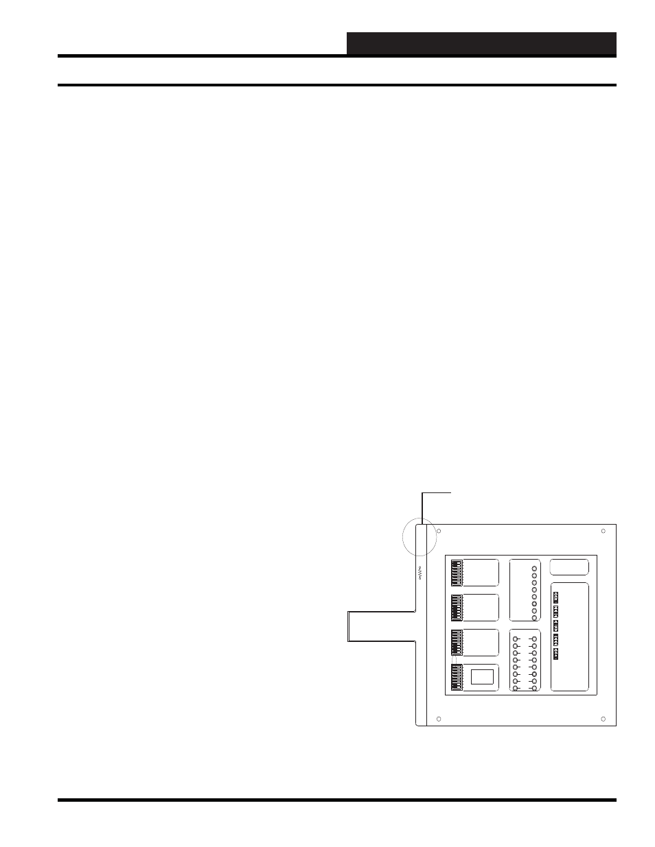
The analog inputs are usually wired to the “+V” and “ATI” (Actual
Temperature In) terminals on the SAT III controller (three wire
sensors are wired to the “GND” terminal also.) The “+V” terminal
on channels 1-7 are a 12 VDC power source. The “+V” terminal
on channel 8 provides either 12 VDC or 24 VDC depending on
the position of the jumper under the cover near channel 8. To get
12 VDC from the “+V” terminal on channel 8, the jumper must
connect the 12 volt and center terminals. To get 24 VDC, the
jumper must connect the 24 volt and center terminals.
A
thermistor and
20 mA sensor can be used on the SAT III
controller. You choose the type of sensor to be used by selecting
the appropriate jumper (located under the SAT III cover). The
choices are Thermistor, 0-10 V, 0-5 V, 0-1 V and Jumper A1 used
J01, A2 used J02 and so on up to A8 uses J08.
8
7
SAT ADDRESS
2
1
4
8
A 3 WIRE ROOM SENSOR WILL NOT
REQUIRE A LOAD RESISTOR WHEN SET
FOR A 1 VOLT INPUT.
WattMaster Controls Inc.
BINARY
INPUTS
BINARY
INPUTS
L8
ON OFF
128
32
16
64
L4
L3
L2
L1
L6
L5
L7
L11
L12
ON OFF
L10
L9
ON OFF
L15
L16
L14
L13
C
H
4
3
5
6
2
1
LOCAL SET
STATUS 2
STATUS 3
STATUS 1
HSS XMIT
LOCAL SET
LOCAL SET DISABLE
BATT ON/ OFF
PULSE INPUT
OPTION 1
TEST
OPTION 3
OPTION 2
ON OFF
STATUS
HSS REC
SAT XMIT
SAT REC
ANALOG INPUT
JUMPER SELECTION
A 2 WIRE ROOM SENSOR WILL REQUIRE
A 300 OHM LOAD RESISTOR WHEN SET
FOR A 1 VOLT INPUT.
A 4 TO 20 mA SENSOR WILL REQUIRE A
50 OHM LOAD RESISTOR WHEN SET FOR
A 1 VOLT INPUT, OR A 250 OHM LOAD
RESISTOR WHEN SET FOR A 5 VOLT INPUT.
CURRENT
INPUT
THERMISTOR
INPUT
0 - 1V
0 - 5V
0 - 10V
THERM
0 - 1V
0 - 5V
0 - 10V
THERM
0 TO 10V
INPUT
0 TO 5V
INPUT
0 TO 1V
INPUT
0 - 10V
0 - 1V
0 - 5V
0 - 10V
THERM
0 - 1V
0 - 5V
THERM
0 - 1V
0 - 5V
0 - 10V
THERM
PROGRAMMABLE CONTROLLER
SAT III
H
C
COM
CHANNEL
2
1
3 4
2
1
3 4
5 6 7 8
5 6 7 8
V
OUT
GND
L
O
A
D
+V
ATI
Jumper (Under Cover)
Data Entry Sequence and Analog Inputs