13b. wcc iii - mcd2 installation guide, Rs-485 communications wiring – WattMaster WM-WCC3-TGD-01B User Manual
Page 619
13B. WCC III - MCD2 INSTALLATION GUIDE
WCC III Technical Guide
13B-7
RS-485 Communications Wiring
The WCC III System RS-485
Communications Wiring
The WCCIII-MCD2 can communicate with up to 239 satellite
controllers via a two-wire RS-485 communication loop. On
the bottom side of the WCCIII-MCD2 there are four RS-485
communication loop ports that come as standard. Each one of
these communications loop ports can communicate with up to 60
satellites for a total of 120 satellites.
The two-wire RS-485 communication loop should be stranded 2
wire twisted pair of 18-gauge wire with a shield wire, and it also
must be plenum rated were applicable. The use of stranded wire is
mandatory to ensure a good connection with the ¼ inch Sta-Con
connectors which are used to terminate the wires at the satellite
controllers. The RS-485 communication wire does not have to be
run from each satellite controller back to the WCCIII-MCD2, but
rather the RS-485 communication wire can be “daisy-chained,”
which means that only one twisted pair of wires is connected to
each of the WCCIII-MCD2 communications loops. The maximum
allowable length of wire from the WCCIII-MCD2 to the farthest
satellite is 4000 feet per RS-485 communications loop.
NOTE:
A length greater than 4000 feet is allowed under
certain circumstances. Consult the factory for assistance if the
communications loop required for your application will exceed
4000 feet.
The RS-485 wire specifi cations are generally a stranded 18-
gauge - 2 wire twisted pair with shield. 18-gauge stranded wire is
mandatory to ensure a good connection with the ¼ inch Sta-Con
connectors, which are used to terminate the wires at the WCC III-
MCD2 and at the satellite controllers. The old SAT II Manchester
communications loop was supposed to have used a 2-wire twisted
pair with shield, but this was not used in every installation. This
old SAT II communications loop should not be used for the new
SAT III communications loop. A new RS-485 communications
loop should be ran to each new replacement SAT III controller.
The shield wire must be used on the new SAT III controller, as
it provides a “ground” reference for the RS-485 communication
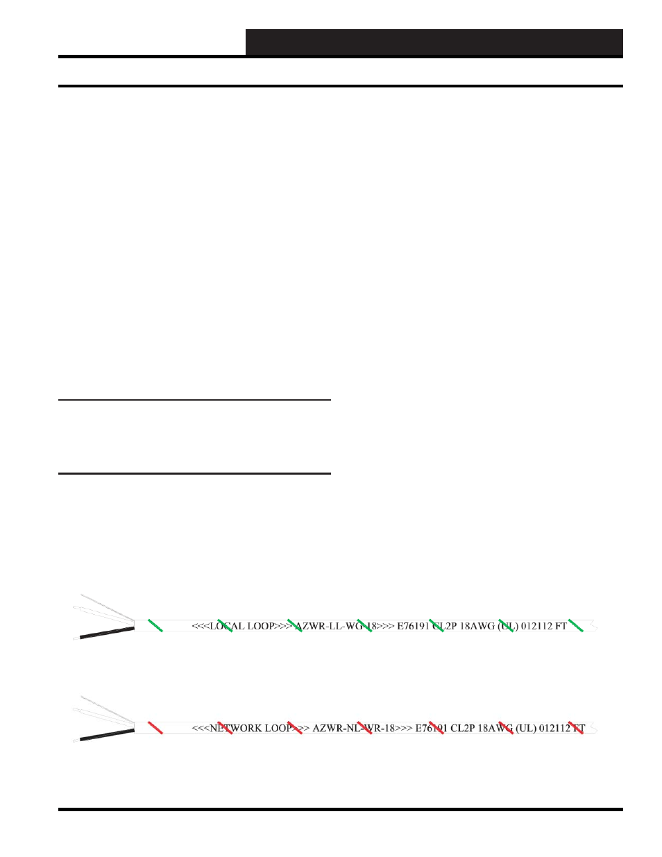
loop. WattMaster Controls sells two versions of 18-gauge - 2-wire
twisted pair with shield communications wire—(1) WattMaster
part #WR-NL-WR-18 which is marked “Network Loop” with
a red stripe for rapid identifi cation. This connection is intended
to run from the WCC III – MCD2 to the SAT III, SAT 3C/D/F,
SAT3P, and then to the next SAT 3 type controllers. (2) WattMaster
part# WR-LL-WG-18 which is marked “Local Loop” with a green
stripe for rapid identifi cation for the TUC loops that run from the
SAT 3C/D/F controllers out to the TUC controllers. “Wire Nuts”
on the RS-485 communications loop should be avoided at all costs.
As an alternative to the “Wire Nuts”, WattMaster Controls has a
Power and Switchable RS-485 communications board, and the
WattMaster part number is PL102224. This Power and Switchable
RS-485 communications board can be thought of as a 24-VAC
power and communication distribution system for the SAT III
communications loop, and this board will aid in initial startup
and future troubleshooting of the SAT III communications loop.
These boards should be used on a fl oor-by-fl oor basis. This Power
and Switchable RS-485 communications board is also available
in a small metal electrical enclosure. The wire that makes up the
communication loop should be shielded. Shielded cable has an
aluminum jacket over the wires that could act as an “antenna”
to carry away any “stray” electrical signals that could interfere
with the communication process. The shield should be grounded
throughout the SAT Loop.
Figure 2: WattMaster Local Loop Wire
Figure 3: WattMaster Network Loop Wire