Cub Cadet 4 x 4 Volunteer User Manual
Page 95
Chapter 3 - Drive System: Drive Shafts and Differentials
91
4.
Manually rotate one rear wheel, with the differ-
ential lock disengaged:
•
If the vehicle is in neutral, the drive shaft leading
from the transfer case to the differential will turn.
•
If the transfer case is in gear, the other rear
wheel should rotate in the opposite direction.
5.
Engage the differential lock and rotate one rear
wheel:
•
If the vehicle is in neutral, both rear wheels will
rotate in the same direction and the drive shaft
leading from the transfer case to the differential
will turn.
•
If the transfer case is in gear, the wheel will be
extremely difficult to turn. The opposite rear
wheel will turn in the same direction, the drive-
shaft will turn, and the driven element of the CVT
will turn.
NOTE: It may take a few degrees of rotation
before the differential lock engages. It will emit
and audible “click” when it does.
6.
If the differential lock fails to engage or disen-
gage as it should, the problem may be internal,
or the problem may be in the linkage. Before
removing the differential, confirm that the prob-
lem does not lie in the linkage.
7.
Confirm that the linkage moves freely through its
range of travel.
When released, the center line of the pin that
connects the shift fork to the linkage should be
1-1/8” (32mm) from the end housing that sup-
ports the sealed carrier bearing.
See Figure 3.5.
Figure 3.5
1.125”
Released
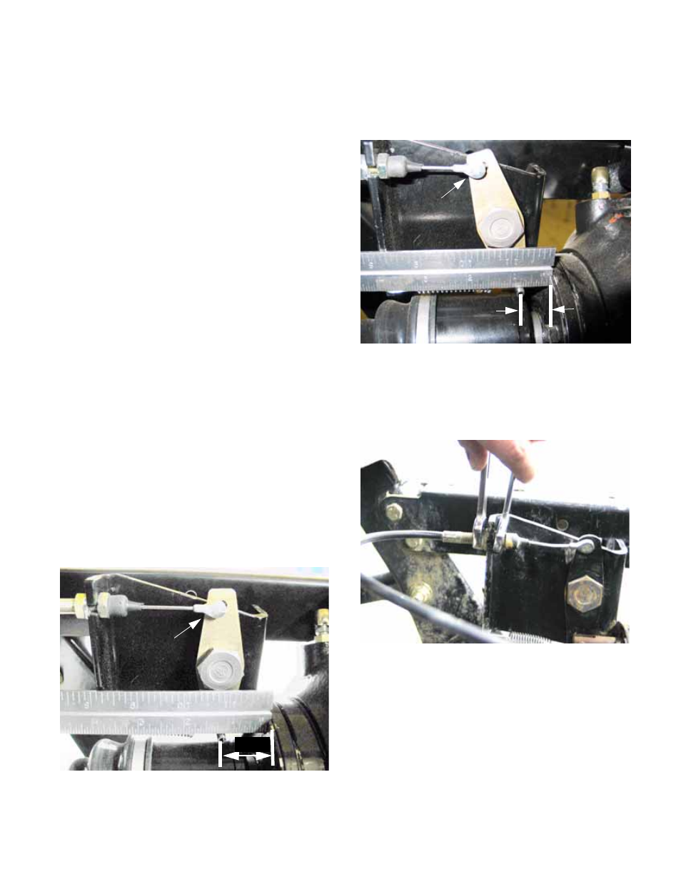
8.
When the differential lock is engaged, there
should be about 3/4” (19mm) from the centerline
of the pin to the end housing that supports the
sealed carrier bearing. See Figure 3.6.
9.
To accommodate this roughly 3/8” (9.5mm) of
travel, the cable should be adjusted so that it is
just slack in the disengaged position.
See Figure 3.7.
NOTE: There will be about 1/2” of free-play as
measured at the top of the control lever.
9.1.
Loosen the jam nut and adjust the cable at the
differential bracket using a pair of 1/2” wrenches.
9.2.
Tighten the jam nut and test the operation of the
differential lock when adjustment is complete.
Figure 3.6
.75”
Engaged
Figure 3.7
Adjustment point