Chapter 2- drive system: cvt and transfer case – Cub Cadet 4 x 4 Volunteer User Manual
Page 27
Chapter 2- Drive System: CVT and Transfer Case
23
6.
The caliper can be adjusted using the screw and
jam nut on the caliper. Us a 7/16” wrench and an
11/16” wrench. See Figure 2.32.
6.1.
After the caliper is in correct adjustment, the link-
age that operates it can be adjusted properly.
6.2.
The parking brake lever pulls on the cable to
engage the brake when the lever is pulled
upward. See Figure 2.33.
•
It moves up in steps that correspond to notches
in a lock plate that the brake lock passes over in
its travel. Full travel = 5 notches.
Figure 2.32
Park brake
caliper
adjustment
Figure 2.33
Park brake
Park brake
cable
switch
Park brake lever
in released position
•
There is a park brake switch mounted beneath
the lever. The contacts within the switch are nor-
mally closed. As the lever is pulled-up, the
plunger extends from the switch, closing the
contacts.
•
Contact closure = 2 notches.
7.
Correct adjustment results in full engagement of
the parking brake before the 5th notch, but
allows the lever to come up far enough to close
the contacts in the switch.
8.
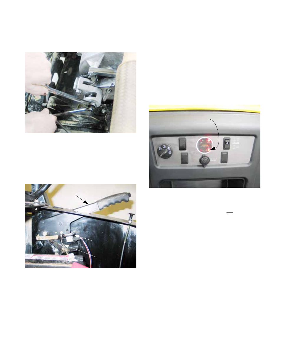
Checking adjustment: See Figure 2.34.
8a. Make the adjustment with the key switch
turned on, but the engine not running, and
the wheels chocked.
8b. Release and reapply the parking brake.
8c. As the bake lever passes the second
notch, the brake light on the instrument
cluster should illuminate. If the transfer
case is not in neutral, an alarm should
sound as well. At this point the slack
should be out of the parking brake cable,
and the arm on the caliper just beginning
to move.
9.
By the third notch, drag should be noted when
the drive shaft leading to the rear differential is
turned.
Figure 2.34
Park brake light