Cub Cadet 4 x 4 Volunteer User Manual
Page 113
Chapter 3 - Drive System: Drive Shafts and Differentials
109
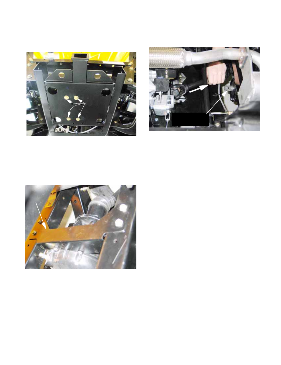
3.
Remove the four bolts that hold the bottom of the
rear differential to the frame using a 9/16”
wrench. See Figure 3.53.
3.1.
Remove two bolts that hold the differential hous-
ing to the torque bracket using a 13mm wrench.
3.2.
Remove the rear differential torque bracket from
the frame using a 1/2” wrench.
See Figure 3.54.
4.
Slide the differential back, allowing the driveshaft
to disconnect from one end.
Figure 3.53
Rear differential
mounting bolts
Accessible from beneath vehicle
Figure 3.54
Torque
bracket
5.
Once disconnected, remove the driveshaft.
See Figure 3.55.
6.
Assembly notes:
•
Inspect the splines and shaft seals before install-
ing the drive shaft. Make any needed repairs
before reassembly.
•
Apply anti-seize compound to the splined joints
on assembly.
•
Replace any worn components before reassem-
bly. If the self-locking feature of any of the nuts
is worn, replace the nuts or use thread locking
compound such as Loctite
R
242 (blue).
•
Apply permanent thread locking compound such
as Loctite
® 262 (red) to the bolts that fasten the
torque bracket to the differential housing.
•
Reverse the removal procedure to install the
rear drive shaft.
•
When locating the front differential, install all of
the hardware that secures the differential and
torque bracket, then go back and tighten it.
•
Check the level of the gear lube in the differen-
tial. Top-up if needed before running the vehicle.
•
Tighten the hardware to the torques specified in
the accompanying table:
Figure 3.55
Rear
drive shaft
Rear differential
pinion spline