Cub Cadet 4 x 4 Volunteer User Manual
Page 209
Chapter 7 - Kohler Engine Service Access and Fuel System
205
19.
Attach a lifting apparatus, and carefully raise the
engine. Support the engine without straining
any of the electrical connections.
See Figure 7.32.
NOTE: Be careful of the engine oil drain valve.
It hangs-down slightly beneath the bottom of the
crankcase.
20.
Disconnect the remaining wires between the
engine and the vehicle. See Figure 7.33.
•
Unplug the engine harness from the main wiring
harness.
•
Disconnect the heavy gauge black ground cable
and its attached light gauge green ground wire
from their attachment point on the upper starter
bolt using a 10mm wrench.
Figure 7.32
Engine is
lifted and
supported for
final disconnection
of wires
Figure 7.33
Engine
harness
Vehicle harness
21.
Remove the engine completely, placing it on a
strong workbench or stable work platform.
22.
Prior to engine installation, check all the service
points on the engine that are easily assessable
while it is removed.
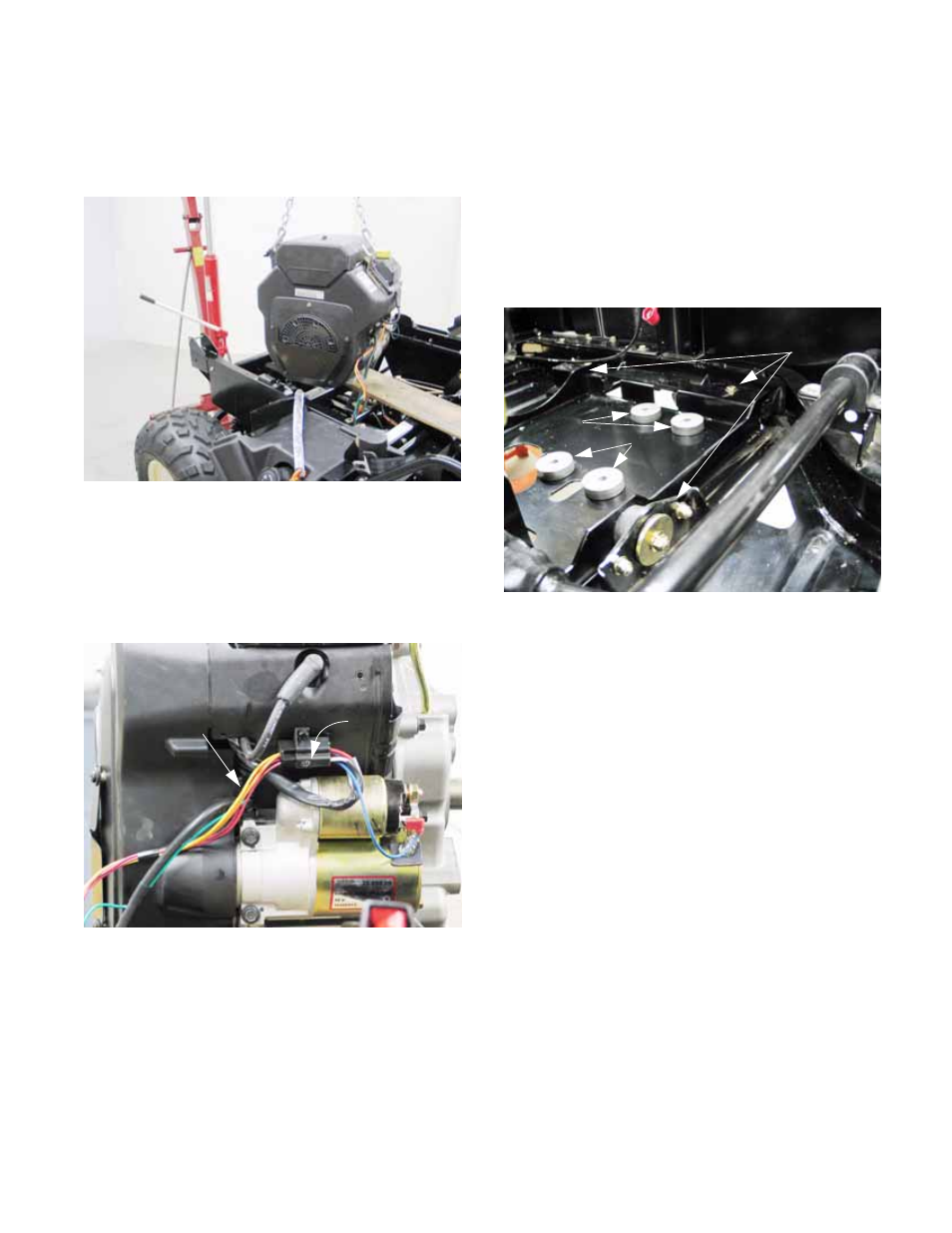
23.
Prior to engine installation, check all of the ser-
vice points on the chassis that are easily
reached while the engine is removed.
See Figure 7.34.
•
Check the rubber isolator mounts that connect
the drive system cradle to the frame. Replace
any that are suspect.
•
The metal spacers that the engine rests on can
be held in place during engine installation with
silicone RTV sealant or automotive trim adhe-
sive.
Figure 7.34
Engine tray
isolator mounts
Engine
mounting spacers