Brake push rod adjustment, Chapter 6 - hydraulic brakes – Cub Cadet 4 x 4 Volunteer User Manual
Page 178
Chapter 6 - Hydraulic Brakes
174
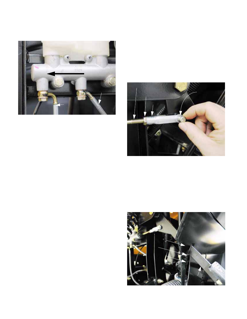
The brake hydraulic system is divided into two circuits:
front and rear. See Figure 6.3.
•
The bore of the master cylinder contains two pis-
tons on a common shaft.
•
The front piston powers the front brakes through
the front fitting on the master cylinder. The rear
piston powers the rear brakes through the rear
fitting on the master cylinder.
•
The reservoir is partitioned into two sections.
Each section feeds one port in the master cylin-
der bore. The forward section feeds the front pis-
ton in the master cylinder. The rear section
feeds the rear piston in the master cylinder.
•
Because all four wheels have disc brakes,
hydraulic action is direct. There are no compen-
sators, balancers, or apportioning valves.
BRAKE PUSH ROD ADJUSTMENT:
•
In the course of normal operation, brake adjust-
ment should not be necessary.
•
If brake adjustment does become necessary,
check the system for wear, damage, and leaks.
3.
To make an adjustment: loosen the brake cle-
vis jam nut using a 13mm wrench, while holding
the brake actuator rod with a 6mm wrench.
See Figure 6.4.
4.
Rotate the brake actuator rod in or out of the
brake yoke to make adjustments, then lock in
the adjustment using the jam nut.
5.
The linkage is correctly adjusted when the bot-
tom of the pedal arm is even with the seam
where the top of the kick panel meets the bottom
of the under-dash support. 1/8”-1/4” (3.2-6.4mm)
free play is normal. See Figure 6.5.
Figure 6.3
Front chamber Rear chamber
Front wheel
brake circuit
Rear wheel
brake
circuit
Front of vehicle
Figure 6.4
Clevis pin
Brake push rod
Jam nut
Yoke
Figure 6.5
Pedal arm
Under-dash support
Seam
Kick panel