Cub Cadet 4 x 4 Volunteer User Manual
Page 205
Chapter 7 - Kohler Engine Service Access and Fuel System
201
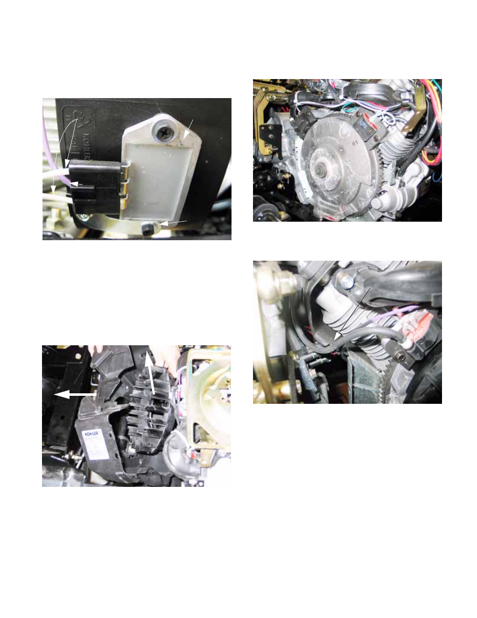
9e. Remove the screws that hold the voltage
regulator and it’s ground strap to the
engine using an 8mm wrench.
See Figure 7.19.
NOTE: It is not necessary to disconnect the
wires from the voltage regulator.
9.6.
Remove the remaining 6 screws that hold the
cooling shroud and lift brackets to the engine.
9.7.
Pull the cooling shroud far enough away from
the engine to allow the fan to be removed from
behind it. See Figure 7.20.
NOTE: on installation, tighten the cooling fan
screws to a torque of 88 in-lbs. (9.9 N-m).
Figure 7.19
Voltage
regulator
Ground
strap
White wires:
stator out-put
Violet wire
Regulator/
rectifier out-put
Figure 7.20
Pull cooling
fan shroud
Remove
fan
9.8.
Remove the fan, followed by the cooling shroud.
See Figure 7.21.
9i. Installation notes: See Figure 7.22.
•
Reverse removal process to assemble.
•
Carefully route and secure all wiring so it does
not get pinched or chafed by other engine parts.
•
Position the shrouds correctly: the cooling
shroud fits above the yellow-zinc coated valley
shroud and inside of the black cylinder shrouds.
•
Make sure the voltage regulator and its ground
strap are securely mounted.
•
Double-check all electrical connections, confirm
that no hazardous conditions will arise from
operating the engine, and briefly test-run the
vehicle before installing the fender, splash
shield, and engine cover.
Figure 7.21
Figure 7.22
Proper wire routing