Chapter 5 - rear suspension – Cub Cadet 4 x 4 Volunteer User Manual
Page 170
Chapter 5 - Rear Suspension
166
6c. Drive the bushing out of the arm.
6d. Clean and lubricate the bore that the bush-
ing was driven out of.
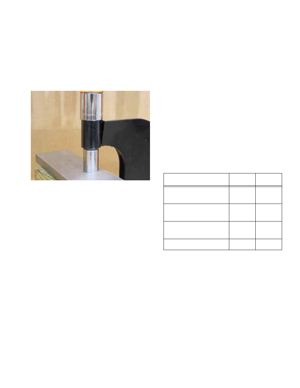
6e. Reverse the positions of the arbors to
drive the replacement bushing in. Press it
until the outer steel sleeve of the bushing
is flush with the edge of the bore.
See Figure 5.18.
6f. Repeat the process for the second bushing
on the control arm.
NOTE: Control arm bushing part numbers are
not shown in the published Illustrated Parts List.
They can be ordered individually as
part # 741-04107
7.
Fasten the control arm to the frame of the vehi-
cle. The brake line should go over the top of the
arm. Do not tighten the nuts at this point.
8.
Re-connect the bottom of the spring and damper
unit to the control arm, tightening the nuts at
both ends of the spring and damper unit to a
torque of 42-64 ft-lbs (60-88 N-m).
9.
Prop the control arm so that it is roughly horizon-
tal, then tighten the hub fasteners to a torque of
32-36 ft-lbs. (43-49 N-m).
NOTE: This will lock the bushings near the static
ride height so that they are not under a constant
torsional load (pre-loaded).
10.
Fasten the brake line to the upper control arm.
11.
Install the wheel, and tighten the lug nuts to a
torque of 75 ft-lbs (102 N-m).
12.
Lower the vehicle to the ground.
13.
Check alignment, and test drive the vehicle in a
safe area before returning it to service.
Figure 5.18
Pressing new
bushing into arm
Item
ft-lbs
N-m
Hub-to-Control Arm
Bolts
32-36
43-49
Control Arm to Frame
Bolts
32-36 43-49
Axle Nut
150-
165
203-
223
Lug Nuts
75
102