Chapter 2- drive system: cvt and transfer case – Cub Cadet 4 x 4 Volunteer User Manual
Page 38
Chapter 2- Drive System: CVT and Transfer Case
34
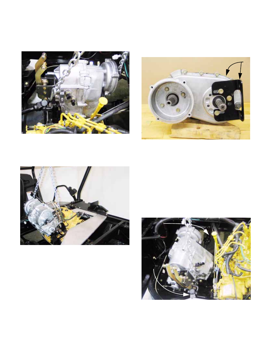
20.
Attach a lifting apparatus to the transfer case,
being careful not to fowl the linkages.
See Figure 2.64.
21.
Carefully lift the transfer case and brackets out
of the vehicle, disconnecting the driveshafts as it
comes up. See Figure 2.65.
22.
If the transfer case is to be disassembled, it is
best to simply leave the brackets attached to the
housing, so that their position is not disturbed.
23.
If the transfer case is to be replaced, match-
mark the position of each mounting bracket so
that it can be installed in an identical position on
the new transfer case. See Figure 2.66.
24.
Installation Notes: Transfer Case Alignment and
Positioning.
24a. Apply a sparing amount of anti-seize
compound to the splined joints at the
transfer case end of each driveshaft.
24b. Use a lifting apparatus to suspend the
transfer case in the engine bay.
24c. Carefully lower the transfer case into posi-
tion, connecting the front and rear drive-
shafts as it is lowered. See Figure 2.67.
24d. Connect the transfer case wiring harness
to the two neutral safety switches before
securing the transfer case to the tray.
Figure 2.64
Figure 2.65
Figure 2.66
Transfer case
Mounting bracket
Figure 2.67
Rear drive
shaft
Front drive shaft