Cub Cadet 4 x 4 Volunteer User Manual
Page 120
Chapter 3 - Drive System: Drive Shafts and Differentials
116
2.
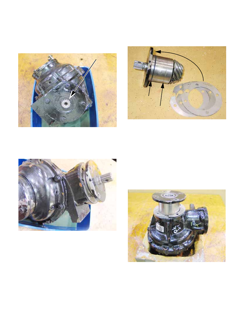
To remove the pinion cartridge:
2a. Remove the four screws that secure the
cartridge using a 1/2” wrench.
See Figure 3.71.
2b. Pull the cartridge off of the main housing.
It may be necessary to shock it with a soft
drift. See Figure 3.72.
NOTE: The pinion depth is set using 1.0mm
shims under the cartridge mounting flange.
NOTE: The cartridge does not seal to the
mounting surface. An O-ring seal on the body of
the cartridge seals against the pinion bore in the
left side (large) housing.
2c. Keep track of the number of shims on each
cartridge if the differential is disassem-
bled. See Figure 3.73.
2d. Beneath the input shaft seal is a crimp nut.
The tightness of the nut sets the pinion
bearing pre-load. With the seal removed,
correct pinion bearing pre-load should
result in pinion shaft drag of 2-3 in-lbs.
(.23-.34 N-m).
3.
Remove the left side bearing cartridge.
3a. Remove the four screws that secure the
left side bearing cartridge using a 9/16”
wrench. See Figure 3.74.
NOTE: The semi-circular plate that is held by
two of the screws
3b. Lift the bearing cartridge out of the housing.
Figure 3.71
Pinion shaft
Figure 3.72
Figure 3.73
O-ring seal
Shims
Pinion cartridge
Figure 3.74