Cub Cadet 4 x 4 Volunteer User Manual
Page 313
Chapter 9 - Electrical
309
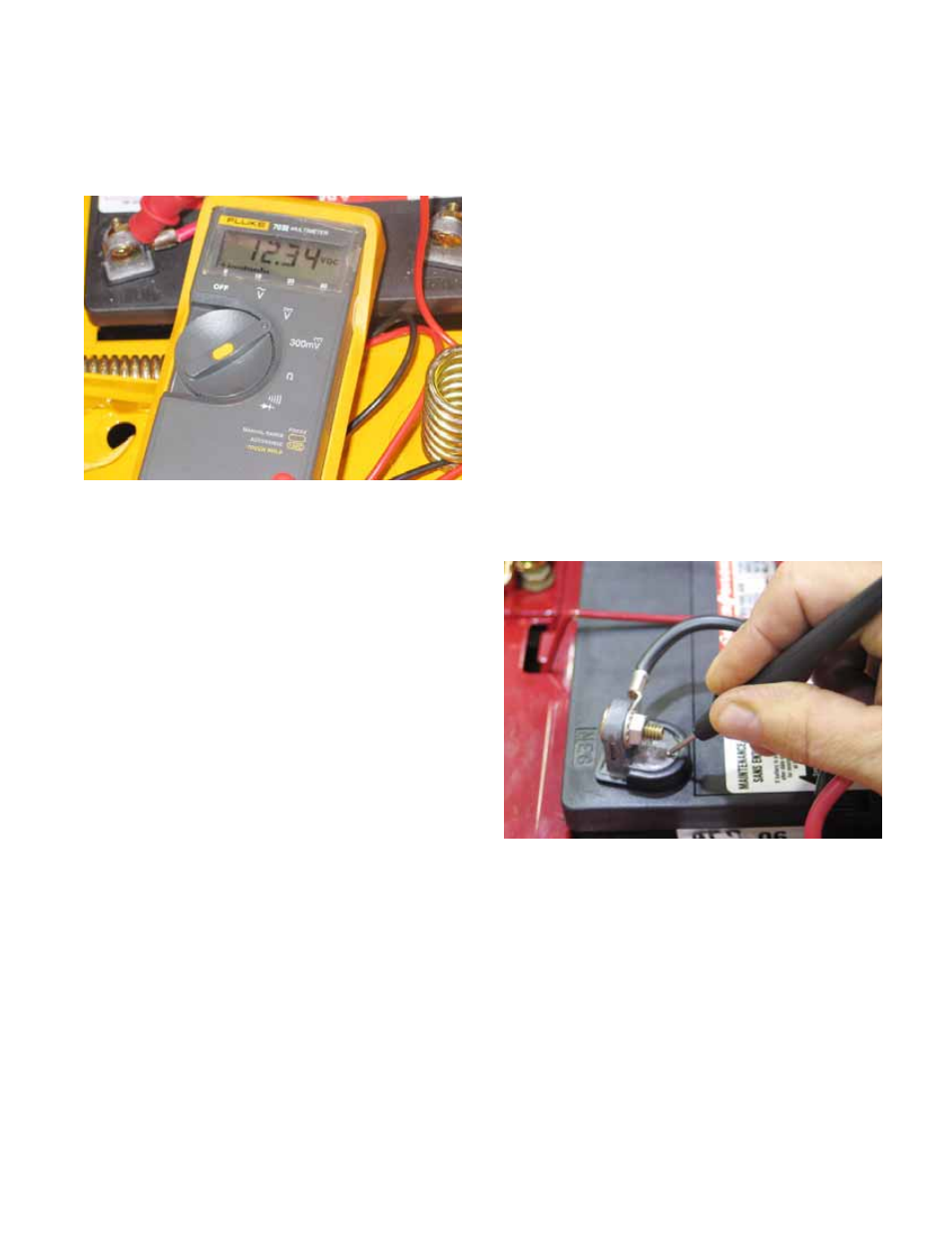
7a. Starting with a fully charged battery and
battery cable connections that are clean
and tight, measure the battery voltage.
See Figure 9.69.
7b. With the circuit energized, start at either
end of the circuit and check for voltage.
•
If starting at the battery-end of a powered circuit,
trace it through until power vanishes.
•
If starting at the far end of a powered circuit,
trace it through to the point that power appears.
•
If there is low voltage at the far end of the circuit,
do a voltage drop test (as described later in this
section) on the circuit to find the source of resis-
tance.
NOTE: When working toward the battery, check
each junction with the connector disconnected,
then re-check with the junction reconnected.
If there is voltage with the connector unplugged
but not when it is connected there is a short
between that point and the last connector tested.
NOTE: When working toward the battery, if one
junction has lost power, but the next connector
has voltage with its junction still connected, there
is an open between the two junctions.
8.
Continue checking each connector until the
other end of the circuit is reached or the fault is
found.
Figure 9.69
Voltage Drop Test
To review:
•
Ohm’s law states that it takes voltage to push
current through a resistance.
•
Kirchhoff’s voltage law states that the sum of all
the voltage drops equals the source voltage.
•
Combining those two laws, we see that any
restriction in a circuit (e.g.: loose connector dam-
aged wire, or corroded terminal) will use up
some voltage as the current is pushed through.
•
A voltage drop test is a way of looking for that
voltage.
•
Because electricity needs to complete a full cir-
cle (circuit), voltage drop tests are useful on both
the positive or the negative side of the system.
•
This text will address the negative side to begin
with. Bad grounds are responsible for as many
electrical failures as the positive side of the sys-
tem, yet the ground side is frequently neglected
by technicians. See Figure 9.70.
IMPORTANT: Ultimately, all current will find its
way back to the negative post of the battery.
9.
To check ground-side voltage drop: set-up a
multimeter to measure 12V DC.
9a. Make a good electrical connection
between the black (-) probe and the nega-
tive post on the battery.
9b. Make a good electrical connection
between the red (+) probe and the sus-
pect point of ground.
9c. Power-up the circuit in question.
Figure 9.70