Cub Cadet 4 x 4 Volunteer User Manual
Page 303
Chapter 9 - Electrical
299
Wiring diagram or schematic
•
A wiring or a schematic diagram, and the ability
to read it are very important in troubleshooting a
circuit. The diagram shows how the circuit was
designed and what paths the electricity is sup-
pose to flow.
Fused jumper wires
•
Fused jumper wires are handy to help find bad
grounds or to jump across switches for testing
purposes.
CAUTION: Only use fused jumper wires. If there
is a short in the circuit, using an unfused jump
could damage components in the circuit.
Test lights
•
Test lights are used as a quick way to verify volt-
age at a point in a circuit. Like DVOMs, they
come in a wide variety from many manufactur-
ers.
•
The most basic test lights simply use the current
being checked to light an incandescent lamp.
These should not be used on any equipment
that has or may have solid-state circuitry.
The power necessary to light the bulb is more
than many solid-state circuits were designed to
handle. Components will be destroyed in the
process of testing them. See Figure 9.51.
•
If a test light is used at all, it should have “high-
impedance”, indicating that it only takes a sam-
ple of the electricity being tested, and illuminates
an LED to indicate the presence of power.
Figure 9.51
Hi impedance test light: Incandescent
GOOD test light:
CAUTION
•
Some high impedance test lights are capable of
indicating whether the current being sampled is
AC or DC.
Self-powered continuity lights
•
Continuity lights can indicate whether a circuit is
complete or not, but they give no indication of
resistance. They are handy for finding point-
break when static-timing some older engines,
but have largely been replaced by DVOMs.
•
There are some powered high-impedance test
lights on the market that have a continuity fea-
ture, and some technicians like the fact that they
can be less bulky than a DVOM.
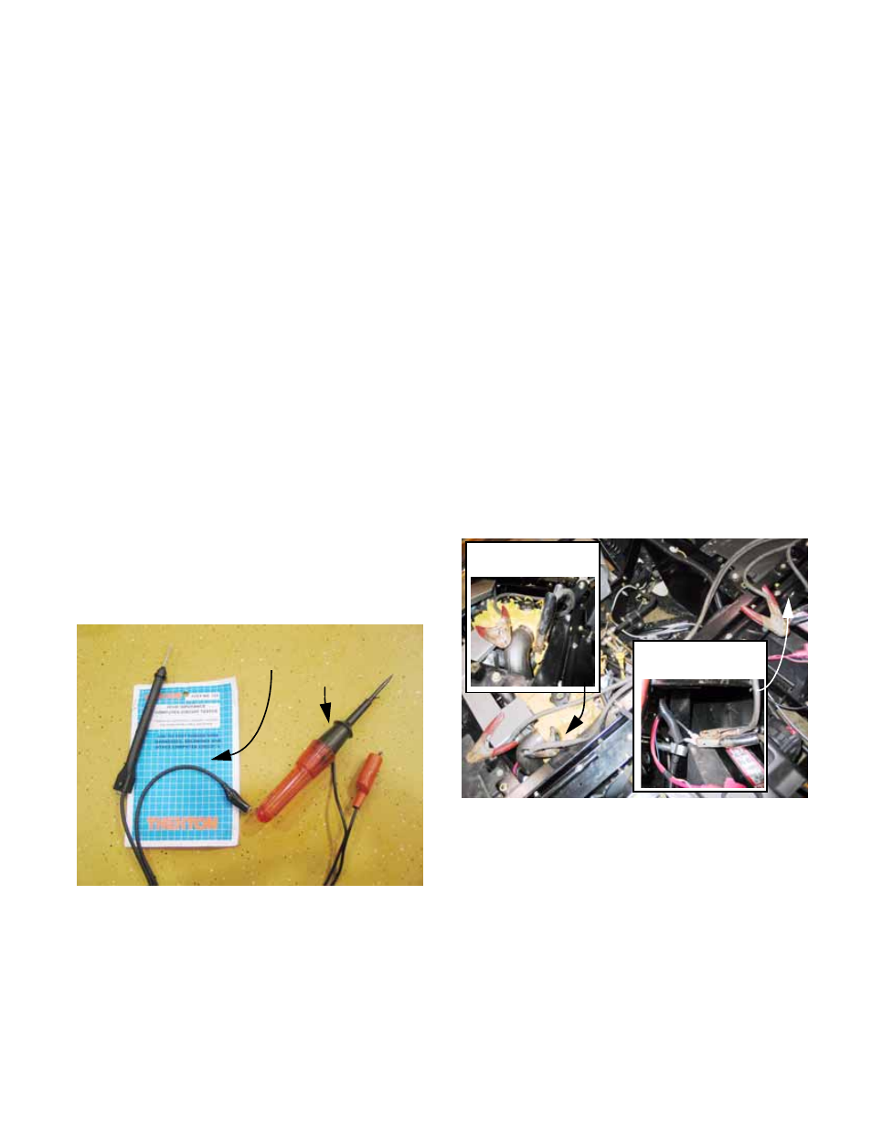
Battery Jumper Cables
•
The obvious use: jumper cables can be used to
jump-start equipment to get it into the shop. This
is not recommended for any fuel injected Kohler-
powered equipment.
•
The clever use: If the technician suspects that
there is resistance on the ground side of the sys-
tem, a quick-and-dirty test can be made using
jumper cables. See Figure 9.52.
•
Connect one cable clamp to the negative post of
the battery, and connect the clamp at the other
end of the same cable to the engine block.
•
If there is an immediate difference in starter
motor performance, use the voltage drop tech-
nique discussed later in this section to identify
the source of the resistance.
Figure 9.52
Inset:
Block connection
Inset:
Battery connection