Cub Cadet 4 x 4 Volunteer User Manual
Page 145
Chapter 4 - Front Suspension and steering
141
3.
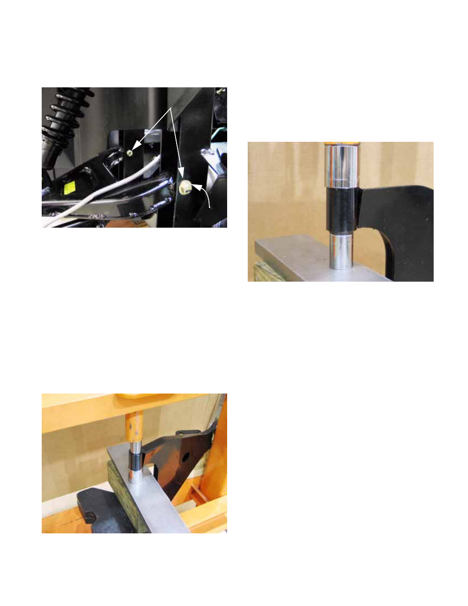
Remove the bolts that fasten the upper control
arm to the frame using a pair of 9/16” wrenches.
See Figure 4.40.
NOTE: Both bolts enter from the front of the
vehicle. Only the foremost of the two bolts has a
washer under its head.
4.
Lift the upper control arm out of the vehicle.
5.
To replace the bushings:
5a. Fixture the control arm on a suitable press
so that the one arbor supports the arm but
does not prevent the bushing from being
driven out.
5b. A second arbor of roughly 1” (2.5cm) out-
side diameter should be positioned to
drive against the outside shell of the bush-
ing. See Figure 4.41.
Figure 4.40
Upper control arm bolts
Washer
(front only)
Figure 4.41
Pressing bushing out
of the arm into the
hollow of the socket
(arbor)
5c. Drive the bushing out of the arm.
5d. Clean and lubricate the bore that the bush-
ing was driven out of.
5e. Reverse the positions of the arbors to
drive the replacement bushing in. Press
it until the outer steel sleeve of the bush-
ing is flush with the edge of the bore.
See Figure 4.42.
5f. Repeat the process for the second bush-
ing on the control arm.
NOTE: Control arm bushing part numbers are
not shown in the published Illustrated Parts List.
They can be ordered individually as
part # 741-04107
6.
Fasten the control arm to the frame of the vehi-
cle. The brake line should go over the top of the
arm. Do not tighten the nuts at this point.
7.
Re-connect the bottom of the spring and damper
unit to the control arm, tightening the nuts at
both ends of the spring and damper unit to a
torque of 42-64 ft-lbs (60-88 N-m).
8.
Prop the control arm so that it is roughly horizon-
tal, then tighten the fasteners to a torque of 32-
36 ft-lbs. (43-49 N-m).
NOTE: This will lock the bushings near the static
ride height so that they are not under a constant
torsional load (pre-loaded).
9.
Secure the ball joint stud to the hub assembly,
tightening the nut to a torque of 22-28 ft-lbs (30-
38 N-m).
10.
Fasten the brake line to the upper control arm.
Figure 4.42
Pressing new
bushing into arm