Chapter 6 - hydraulic brakes – Cub Cadet 4 x 4 Volunteer User Manual
Page 184
Chapter 6 - Hydraulic Brakes
180
7.
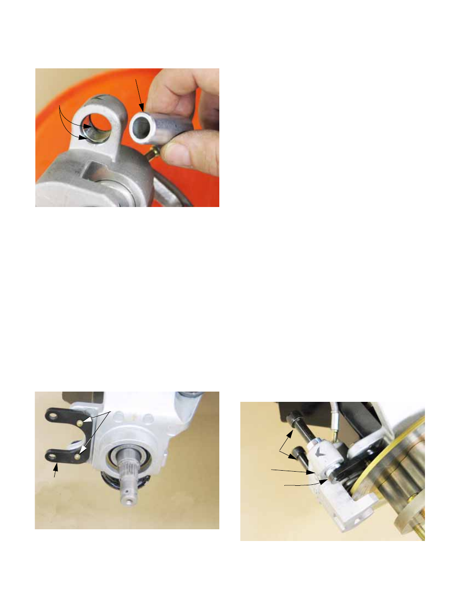
Check the slide bushings. See Figure 6.17.
•
The slide bushings should be clean, and free to
slide in the mounting bores of the caliper.
•
O-rings provide a seal between the bushings
and the caliper.
•
Uneven pad wear may indicate that the caliper is
not sliding as designed, and the slide bushings
require attention.
•
On assembly: lubricate the O.D. of slide bush-
ings or the I.D. of the bore with a high tempera-
ture synthetic grease that is meant for use on
brake calipers. Typical of these products is
Versachem Part Number 26111, available
through NAPA® as Item #BK7653072.
8.
Check the brake caliper bracket for damage or
loose hardware. See Figure 6.18.
9.
Check the brake rotor as described in the follow-
ing section of this manual before reinstalling the
caliper. Replace the rotor if necessary.
10.
Installation notes: brake caliper
See Figure 6.19.
NOTE: A brake pad service kit is available as
959-04116. This kit is not shown in the Illus-
trated Parts List. The kit consists of: two brake
pads, two slide pins, and two retaining rings.
This will service a single wheel. Two kits are
required for an axle. The same kit is used for
front and rear wheels
10a. If brake rotor has been removed, install
the brake rotor.
10b. Clean any grease, oil, or fingerprints from
the brake rotor.
10c. Apply a very small amount of anti-seize
compound to the shoulders of the caliper
mounting bolts (slide pins).
10d. Position the caliper on the caliper bracket,
and insert the slide pins just far enough to
hold the caliper in place.
10e. Slip the piston-side brake pad into place,
pushing the slide pins through far enough
to hold the piston-side pad.
10f. Slip the outside pad into place, and com-
plete the installation of the slide pins:
push them in until the threads engage,
then tighten them to the specified torque
using a 3/8” allen wrench.
10g. Install the C-clips that secure the brake
pads. If there is any question of the condi-
tion of the C-clip replace it with a new one.
Figure 6.17
Slide bushing
O-ring seals
Figure 6.18
Brake caliper
bracket (rotor
removed for
visibility)
If removed, apply
thread-locking sealant
such as Loctite
®
262 (red)
to threads, and tighten
to a torque of 22-26 ft-lbs
(30-35 N-m)
Figure 6.19
Slide pins
Caliper
Inside pad