Cub Cadet 4 x 4 Volunteer User Manual
Page 283
Chapter 9 - Electrical
279
7.
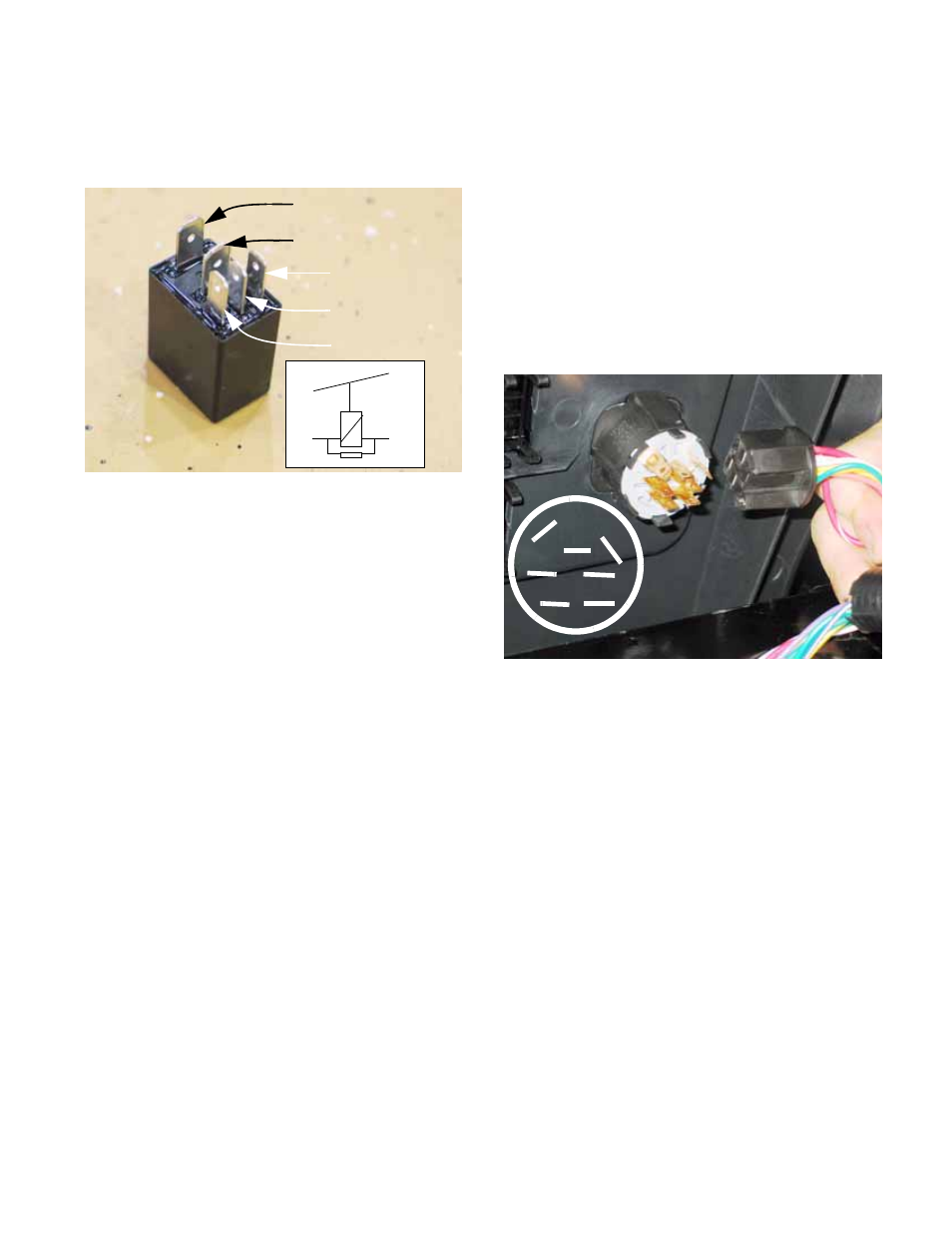
Relay Function
•
Most of the relays used on this vehicle have five
pins. See Figure 9.7.
•
Windings: Terminals 1 & 2 are the outer-most of
the row of three small spade terminals.
When one has power and the other is connected
to ground, the relay is energized.
•
Normally, a resistance reading between termi-
nals 1&2 will produce a measurement of about
100
Ω. This is the resistance in the windings
around an iron core that energize an electro-
magnet or a solid-state equivalent.
•
Terminal 3 is a “Common” connection. It may be
connected to power or ground, depending on the
application. It is the large spade terminal near
the edge of the relay.
•
Terminal 4 is the “Normally Closed” contact.
When the relay is not energized, terminal 4 is
connected to terminal 3. When the relay is ener-
gized, this connection breaks.
An Ohm meter should show zero resistance or
“0.0
Ω” between 3 & 4 when the relay is at rest,
and it should read 1.0
Ω or “O.L.” when the relay
is energized.
Figure 9.7
Spade 3 Common
Spade 4 N.C.
Spade 2 Windings
Spade 1 Windings
Spade 5 N.O.
O O
O
O
O O
3 4
5
1 2
Inset:
Circuit diagram’
of relay, printed on the
side of some relays
•
Terminal 5 is the “Normally Open” terminal. It
connects to terminal 3 when the relay is ener-
gized. When 3 & 4 are connected, 3 & 5 are dis-
connected, and vice-versa.
An Ohm meter should show zero resistance, or
“0.0
Ω” between 3 & 4 when the relay is at rest,
and it should read 1.0
Ω or “O.L.” when the relay
is energized.
8.
Key switch: The key switch is mounted in the
dashboard, and is easily removed by unplugging
the electrical connections and squeezing the two
lock tabs to release it from the panel.
See Figure 9.8.
•
Because the key switch in the diesel is partially
obscured by the cooling matrix, it is easier to pull
the switch from the dashboard, then unplug it.
•
Gas and diesel engines both use the same key
switch, but the wire connections to those
switches differ.
•
The diesel engine requires no ground wire, so
the M and G spade terminals on the key switch
are vacant on the diesel applications.
Figure 9.8
G
L
A1
S
A2
M B