Chapter 2- drive system: cvt and transfer case – Cub Cadet 4 x 4 Volunteer User Manual
Page 64
Chapter 2- Drive System: CVT and Transfer Case
60
5c. Install the low-gear shift arm.
5d. Tighten the nuts on both pivot bolts of both
shift arms to a torque of 9 ft-lbs (13 Nm).
5e. Apply a small amount of thread locking
compound such as Loctite® 242 (blue) to
the threaded portion of the shoulder
screws that connect the shift shafts to the
shift arms.
5f. Install the shoulder screws, and tighten
them to a torque of 115 in-lb. (13 N-m).
See Figure 2.151.
5g. Test the operation of the shift arms. It may
be necessary to rotate the input shaft for
internal gear alignment. Return both shift
arms to neutral when finished.
6.
Install the parking brake:
6a. Apply a small amount of thread locking
compound such as Loctite® 262 (red) to
the screws that hold the caliper bracket to
the case.
6b. Apply a small amount of ant-seize com-
pound to the brake shaft.
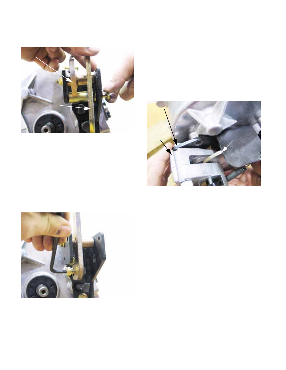
6c. Position the brake caliper and brake rotor
as one assembly, and secure them to the
case. See Figure 2.152.
NOTE: The flat side of the brake rotor faces out.
the shoulder goes toward the case.
6d. Tighten the screws to a torque of 115 in-lb.
(13N-m).
Figure 2.150
F-N-R shift arm
Low range
shift arm
Figure 2.151
Figure 2.152
Brake caliper bracket
Brake
caliper
Brake rotor