Kohler enclosed cvt addendum – Cub Cadet 4 x 4 Volunteer User Manual
Page 74
Kohler Enclosed CVT Addendum
70
•
Tighten the 5/16-18 screws to a torque of 18-22
ft-lbs. (24-30 N-m).
•
Tighten the 3/8-16 screws to a torque of 22-25 ft-
lbs. (30-34 N-m).
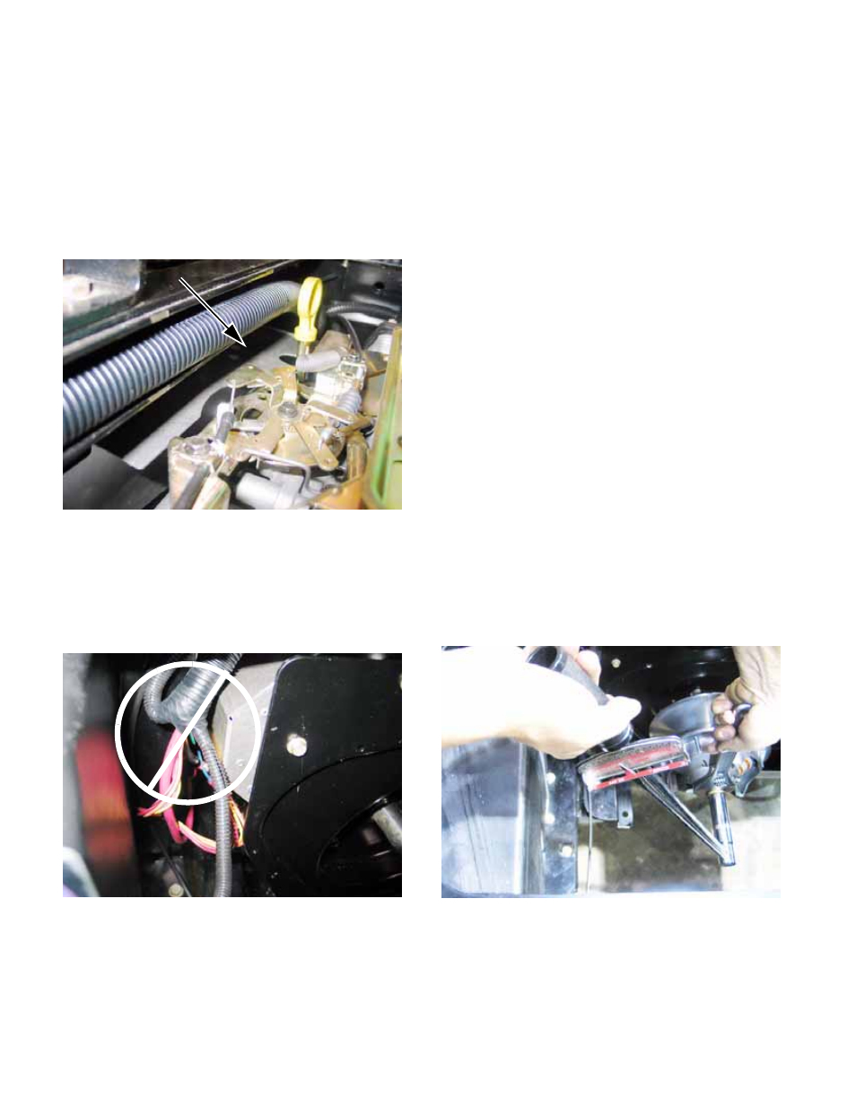
5k. Once the back plate is secured to the
engine and transfer case, check to see
that: The heat shield does not fowl the
engine governor. See Figure 2a.22.
•
Once the back plate is secured to the engine
and transfer case, check to see that the wires
near the starter motor are securely routed a safe
distance from the heat shield and any pinch
points. See Figure 2a.23.
6.
CVT Installation
6a. Prepare the CVT for installation:
•
Clean the shafts and the surrounding area
before installing the CVT.
•
Confirm the presence of the .060” (1.5mm)
spacer on the shaft between the driven element
and the transfer case housing.
•
A small amount of anti-seize compound may be
used on the splined joint between the input shaft
of the transfer case and the driven element.
•
The tapered joint between the driven element
and the crankshaft may be lubricated with a
small amount of multi-purpose grease (Cub
Cadet P/N: 737-3034).
•
Apply a small amount of thread locking com-
pound such as Loctite® 262 (red) to the stud
that will secure the driving pulley.
NOTE: The screw that holds the driven pulley to
the input shaft of the transfer case will be
reused.
The screw that held the driving pulley to the
engine crankshaft will be replaced with the dou-
ble-ended stud.
6b. Fasten the driving pulley to the crankshaft
using the bolt, washer, and shoulder
spacer previously removed on the double-
ended stud. Tighten it to a torque of 35-
36 ft-lbs.(43-49 N-m). See Figure 2a.24.
6c. Secure the driven pulley to the input shaft
using the bolt, washer, and shoulder
spacer previously removed.
Figure 2a.22
Heat shield
Figure 2a.23
Wires against
heat shield
Figure 2a.24