Chapter 2- drive system: cvt and transfer case – Cub Cadet 4 x 4 Volunteer User Manual
Page 48
Chapter 2- Drive System: CVT and Transfer Case
44
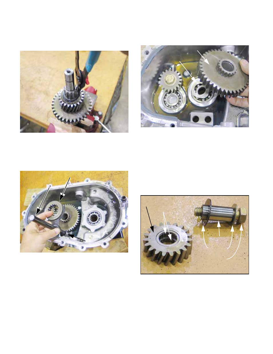
9h. The middle shaft is easily disassembled
using a pair of external snap ring pliers.
See Figure 2.100.
9i. Lift the forward-neutral-reverse shift shaft,
shift yoke, spacer, and shift collar out of
the bore that is closer to the output shaft
bearing. See Figure 2.101.
9j. The 39-tooth reverse gear will be left rest-
ing in the right hand case, separated from
the bearing that carries the middle shaft
by a .030” (0.76mm) washer.
9k. Lift-out the reverse gear and washer.
9l. The reverse idler is the last gear left in the
case, secured by a 1/2”-13 grade-8 cap
screw and flat washer. Remove it using a
3/4” wrench.
9m. The reverse idler contains a pair of roller
bearings that ride on a hardened tube.
The tube passes-through a washer that
isolates the reverse idler from the case.
See Figure 2.103.
NOTE: If new input shaft or reverse idler that
mates with it are installed in the transfer case,
orientation of the gears on the shaft is unimpor-
tant. Once a wear pattern is established on the
gear teeth, orient the gears to maintain that wear
pattern. Mark the gear if necessary.
Figure 2.100
Figure 2.101
F-N-R shift collar
F-N-R shift shaft
Spacer
Figure 2.102
Reverse gear
washer
Figure 2.103
Reverse Idler
Roller bearings
Steel tube
Washers
Gr.8 bolt