Engine and transfer case tray – Cub Cadet 4 x 4 Volunteer User Manual
Page 275
Chapter 8 - Caterpillar Engine and Related Systems
271
* Install with releasable threadlocking compound
such as Loctite®
242 (blue).
** Install with permanent threadlocking compound
such as Loctite
®
262 (red).
Item
ft-lbs
N-m
Engine to tray &
Engine to bracket
32-36
43-49
Engine bracket to tray
13
18
Engine / Transmission
plate to engine plate
13*
18*
Engine / Transmission
Plate to transfer case
12*
16*
Tapered-shaft adaptor
to flywheel
32-36**
43-49**
Driving element to
engine adaptor
32-36**
43-49**
Driven element to
transfer case input
shaft
70-80**
95-
109**
Exhaust screws
13
18
ENGINE AND TRANSFER CASE TRAY
NOTE: Because of clearance issues and the
complexity of the removal process, it is not likely
that a technician would remove the tray with the
engine and transfer case still attached.
The primary reason to remove the tray would be
to replace or repair the tray itself.
To remove the tray, first remove the engine as
described in the ENGINE REMOVAL section of
this chapter, and remove the transfer case as
described in the CVT and TRANSFER CASE
chapter of this manual.
1.
Checking the mounts:
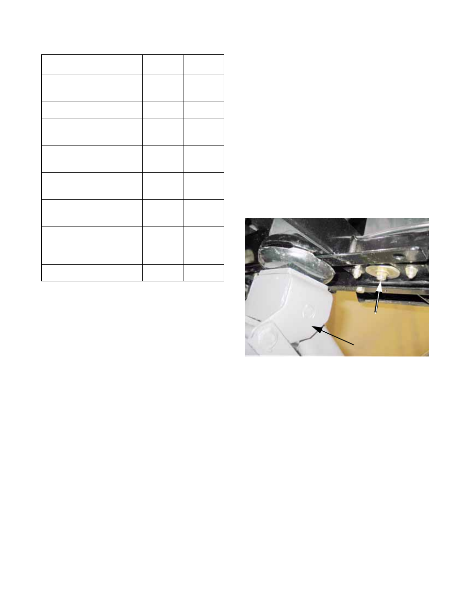
1a. Lift up on the engine tray using a jack or
pry-bar to check the condition of the rub-
ber mounts. See Figure 8.142.
•
The four corner-mounts are installed in compres-
sion. As they fatigue, the bolt that passes
through the center of each mount will loosen
slightly.
1b. If the tray has play when lifted, the mounts
are fatigued. If the fatigue is slight, the
bolts may simply be tightened.
1c. If the fatigue is more than can be made-up
for by tightening hardware, the mounts
should be replaced.
NOTE: The passenger’s side mounts are
loaded under acceleration. They will show wear
before the driver’s side mounts in most applica-
tions.
NOTE: The mounts will degrade if they are per-
meated with fuel or oil.
Figure 8.142
With weight relieved,
check for looseness
here
Jack